Table of Contents
Advertisement
Quick Links
LIST OF PRODUCTS
Digital Multimeter
*
Digital AC & AC/DC Clampmeter
*
AC Clamp Adaptor
*
AC/DC Current Adaptor
*
*
Transistorised Electronic Analog & Digital
Insulation Resistance Testers(upto 10 KV)
*
Digital Sound Level Meter & Sound Level
Calibrator
*
Digital contact & Non-contact Type
Tachometer
*
Digital Non-contact (infrared) Thermometer
*
Thermo Hygrometer
*
Thermo Anemometer
*
Wood & Paper Moisture Meter
*
Distance Meter
*
Digital Hand Held Temperature Indicators
*
Digital Lux Meter
*
Network Cable Tester
*
Power Factor Regulator
*
Maximum Demand Controller/Digital Power
Meter
*
Earth Resistance Tester
17, Bharat Industrial Estate, T. J. Road, Sewree (W),
Mumbai-400015. INDIA
Sales Direct: 24156638
Tel.:
(022)2412 4540, 2418 1649
E-mail : kusam_meco@vsnl.net, Website : www.kusamelectrical.com,
Fax:
2414 9659
www.kusam-meco.co.in
An ISO 9001:2008 Company
DIGITAL
MULTIMETER
KM 6030
OPERATION
MANUAL
Advertisement
Table of Contents

Subscribe to Our Youtube Channel
Related Manuals for Kusam-meco KM 6030


Summary of Contents for Kusam-meco KM 6030
- Page 1 AC Clamp Adaptor DIGITAL AC/DC Current Adaptor Transistorised Electronic Analog & Digital MULTIMETER Insulation Resistance Testers(upto 10 KV) KM 6030 Digital Sound Level Meter & Sound Level Calibrator Digital contact & Non-contact Type Tachometer Digital Non-contact (infrared) Thermometer Thermo Hygrometer Thermo Anemometer Wood &...
- Page 2 MULTIMETER DMM users frequently burn their meters by trying KM 6030 to measure current the same way as they measure voltage, Remember, you measure voltage across a circuit, and current through a circuit. When you use the current input, your DMM becomes a lower impedance circuit element.
-
Page 3: Table Of Contents
OVERVIEW Table of Contents Title Page Warning To avoid electric shock or personal injury, read Overview ............1 the “Safety Information” and “Rules for Safe Unpacking Inspection........1 Features............2 Operation”carefully before using the Meter. General Specifications......3 Electrical Specifications......4 Digital Multimeter Model - 6030 (hereafter referred to DC Voltage as “the Meter”) is a 3½... -
Page 4: Features
FEATURES : GENERAL SPECIFICATIONS : Low power consumption CMOS double Display : 3½ digit LCD. Maximum integration, A/D transform integrated circuit, reading 2000 with Auto Zero Calibration, Auto Polarity display, automatic sign and Data Hold, Low Battery & Over range Function annunciators. -
Page 5: Electrical Specifications
DC CURRENT ELECTRICAL SPECIFICATION : Range Resolution Accuracy DC VOLTAGE Range Resolution Accuracy ±(0.8% rdg +2dgts) ±(1.2% rdg + 2dgts) 200 mA ±(2% rdg +5dgts) ±(0.5% rdg + 3dgts) Overload Protection: 0.2A/250 V fuse ±(0.8% rdg + 3dgts) 1000 Max input current : 20A Input Impedance : 10M RESISTANCE Overload Protection : 250V(for 200mV),DC or AC... -
Page 6: Temperature
TEMPERATURE Rules For Safe Operation Range Accuracy Resolution (0.75% rdg + 4dgts) Warning -40°C~400°C ± 1°C (1.5%rdg + 15dgts) ± 400°C~1000°C To avoid possible electric shock or personal injury, and to avoid possible damage to the Meter or to the equipment under test, adhere to the FREQUENCY following rules : Range... -
Page 7: International Electrical Symbols
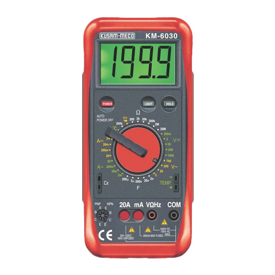
The Multimeter Structure (see figure 1) Rules For Safe Operation (2) Disconnect circuit power and discharge all high -voltage capacitors before testing resistance, 6030 1999 continuity, diodes, current or capacitance. Replace the battery as soon as the battery indicator appears. With a low battery, the Meter might produce false readings that can lead to electric shock and personal injury. -
Page 8: Display Symbols
6) BACK LIGHT SWITCH: Symbol Meaning To turn OFF or ON the back light so that readings Dangerous Voltages. Can be taken in the dark. The battery is low. FUNCTION SELECTOR: Warning : To avoid false To select various functions readings, which could lead to 8) INPUT SOCKET FOR TEMPERATURE possible electric shock or... -
Page 9: Measurement Operation
MEASUREMENT OPERATION Caution : Make sure the Low Battery display is not on, If the value of voltage to be measured is otherwise false readings may be provided. unknown, use the maximum measurement Pay extra attention to the symbol which is located position (1000V) and reduce the range step by besides the input terminals of the Meter before carrying step until a satisfactory reading is obtained. -
Page 10: Ac Current
When AC Voltage measurement has been completed, disconnect the connection between Warning : the testing leads and the circuit under test. To avoid harm to you or damages to the Meter from electric shock, please do not attempt to measure voltages higher than 1000V or 700V rms C. -
Page 11: Dc Current
1) Turn off power to the circuit. Discharge all Warning : High - Voltage capacitors. Never attempt an in - circuit current measurement Insert the red test lead into the mA or 20A where the open circuit voltage between terminals and terminal and the black test lead into the COM ground is greater than 60V DC or 30V rms. -
Page 12: Resistance
Caution To measure resistance, connect the meter as follows If the value of current to be measured is unknown, use the maximum measurement 1) Insert the red test lead into the V terminal and position (20A) and 20A terminal, and reduce the black test lead into the COM terminal. -
Page 13: Capacitance
Capacitance Measurement (see figure 8) Caution : 1) Never connect high voltage to the input Warning Sockets with the switch in Capacitance range. To avoid damages to the Meter or to the equipment 2) Using Capacitance measurement function in a under test, disconnect circuit power and discharge all Live circuit will produce false results and may high-voltage capacitors before measuring... -
Page 14: Frequency
3) Insert the plug with the positive polarity in the The frequency measurement range is 2kHz. positive socket and the negative polarity To measure frequency, connect the Meter as follows : in the negative socket. 1) Insert the red test lead into the V terminal and 4) Set the measurement end of the thermocouple the black test lead into the COM Terminal. - Page 15 When diode testing has been completed, To test a diode out of a circuit, connect the Meter as follows : disconnect the connection between the testing Leads and the circuit under test. 6030 Testing for Continuity To test for continuity, connect the Meter as below : 1.
-
Page 16: Maintenance
Remove the battery from the battery to national standards. compartment. Replace the battery with a new Standard 9V Battery. Rejoin the battery compartment and the case KM 6030 MODEL NO. ___________ bottom, and install the screw. SERIAL NO. ___________ DATE: ___________ ISO 9001... -
Page 17: Warranty
WARRANTY THIS WARRANTY IS BUYER’S SOLE AND EXCLUSIVE REMEDY AND IS IN LIEU OF ALL Each “KUSAM-MECO” product is warranted to be OTHER WARRANTIES, EXPRESS OR IMPLIED, free from defects in material and workmanship INCLUDING BUT NOT LIMITED TO ANY IMPLIED under normal use &...
Need help?
Do you have a question about the KM 6030 and is the answer not in the manual?
Questions and answers