Table of Contents
Advertisement
Quick Links
THIS WARRANTY IS BUYER'S SOLE AND
EXCLUSIVE REMEDY AND IS IN LIEU OF ALL
OTHER WARRANTIES, EXPRESS OR IMPLIED,
INCLUDING BUT NOT LIMITED TO ANY IMPLIED
WARRANTY OF MERCHANTABILITY OR
FITNESS FOR A PARTICULAR PURPOSE.
"KUSAM-MECO" SHALL NOT BE LIABLE FOR
ANY SPECIAL, INDIRECT, INCIDENTAL OR
CONSEQUENTIAL DAMAGES OR LOSSES,
INCLUDING LOSS OF DATA, ARISING FROM
ANY CAUSE WHATSOEVER.
All transaction are subject to Mumbai Jurisdiction.
G 17,Bharat Industrial Estate, T. J. Road,
Sewree (W), Mumbai - 400 015. INDIA.
Sales Direct : (022) 24156638
Tel. : (022) 24124540, 24181649.
Fax : (022) 24149659
Email : kusam_meco@vsnl.net
sales@kusam-meco.co.in
Website : www.kusamelectrical.com
OPERATION MANUAL
DIGITAL
MULTIMETER
KM 6030
Advertisement
Table of Contents

Subscribe to Our Youtube Channel
Related Manuals for Kusam-meco KM 6030


Summary of Contents for Kusam-meco KM 6030
- Page 1 INCLUDING BUT NOT LIMITED TO ANY IMPLIED WARRANTY OF MERCHANTABILITY OR OPERATION MANUAL FITNESS FOR A PARTICULAR PURPOSE. DIGITAL “KUSAM-MECO” SHALL NOT BE LIABLE FOR MULTIMETER ANY SPECIAL, INDIRECT, INCIDENTAL OR KM 6030 CONSEQUENTIAL DAMAGES OR LOSSES, INCLUDING LOSS OF DATA, ARISING FROM ANY CAUSE WHATSOEVER.
-
Page 2: Table Of Contents
TAKE MEASUREMENT CAREFULLY AND YOU’LL Table of Contents SPARE YOUR METER AND YOURSELF, SOME PAIN Title Page Nearly every electrical engineer has a hand held Multimeter. We sometimes take them for granted, until Overview ............1 Unpacking Inspection........1 we damage them or “burn them out” if you incorrectly Features............2 connect your DMM to a circuit or have the DMM on General Specifications........3... -
Page 3: Overview
FEATURES : OVERVIEW ˜ Test lead jack mechanical protection function Warning & full Range over-load protection function. To avoid electric shock or personal injury, read ˜ Low power consumption CMOS double the “Safety Information” and “Rules for Safe integration, A/D transform integrated circuit. Operation”carefully before using the Meter. -
Page 4: General Specifications
ELECTRICAL SPECIFICATION : GENERAL SPECIFICATIONS : Sensing : Average Sensing DC VOLTAGE Display : 3½ digit 1999 counts Range Accuracy Resolution LCD display. with 200 mV 100 mV automatic sign and Function annunciators. ±(0.5%rdg + 3dgts) Digital Size : 28mm(H) 100 mV Over range indication : Highest digit of (1) or (-1) ±(1.0%rdg + 5dgts) -
Page 5: Dc Current
DC CURRENT TEMPERATURE Range Accuracy Range Resolution Resolution Accuracy ±(5.0%rdg + 5dgts) -40°C~0°C ±(1.0% rdg +3dgts) ±(1.0%rdg + 3dgts) 0°C~400°C 1°C ±(1.5% rdg + 5dgts) 200 mA ±(3.0%rdg + 4dgts) 400°C~1000°C ±(2.0% rdg +10dgts) Overload Protection : 0.2A/250V Fuse (No fuse on FREQUENCY 20A range). -
Page 6: Rules For Safe Operation
! Do not operate the Meter under adverse Rules For Safe Operation environmental humid area. To avoid damages The meter comply with IEC 1010-1 CAT I 1000V, and dangerous, do not change the circuit. CAT II 600V and CAT III 300V over voltage ! Periodically wipe the case with a damp cloth and standards. -
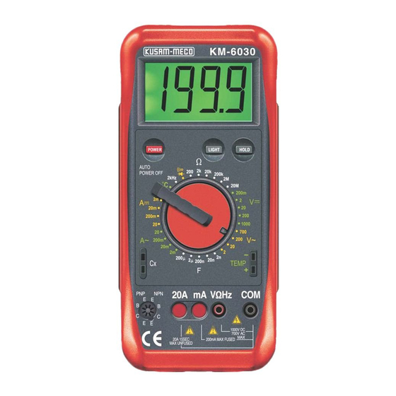
Page 7: The Multimeter Structure
The Multimeter Structure (see figure 1) Display Symbols (see figure 2) KM-6030 1999 . . . (Figure 2) AUTO POWER OFF 20A mA VWHz 1000V DC 750V AC 20A 10SEC MAX UNFUSED 200mA MAX FUSED ( Figure 1) 1) Liquid Crystal Display 2) Data hold switch 3) Rotary switch 4) Temperature jack or inductance jack... -
Page 8: Measurement Operation
MEASUREMENT OPERATION Meaning Symbol Make sure the Low Battery display is not on, Dangerous Voltages. otherwise false readings may be provided. The battery is low. Pay extra attention to the symbol which is located Warning : To avoid false besides the input terminals of the Meter before carrying out measurement. -
Page 9: Ac Voltage
Caution : Warning : If the value of voltage to be measured is To avoid harm to you or damages to the Meter unknown, use the maximum measurement from electric shock, please do not attempt to position (1000V) and reduce the range step by measure voltages higher than 1000V or 750V rms step until a satisfactory reading is obtained. -
Page 10: Ac Current
When AC Voltage measurement has been 1) Turn off power to the circuit. Discharge all completed, disconnect the connection between High - Voltage capacitors. the testing leads and the circuit under test. Insert the red test lead into the mA or 20A terminal and the black test lead into the COM terminal Set the rotary switch to an appropriate... -
Page 11: Resistance
Caution Warning : If the value of current to be measured is Never attempt an in - circuit current measurement unknown, use the maximum measurement where the open circuit voltage between terminals and position (20A) and 20A terminal, and reduce ground is greater than 60V DC or 30V rms. -
Page 12: Capacitance
Capacitance Measurement (see figure 8) To measure resistance, connect the meter as follows 1) Insert the red test lead into the VW terminal and Warning the black test lead into the COM terminal. To avoid damages to the Meter or to the equipment 2) Set the rotary switch to an appropriate under test, disconnect circuit power and discharge all measurement position in W range. -
Page 13: Temperature
3) Insert the plug with the positive polarity in the Caution : positive socket and the negative polarity in the negative socket. 1) Never connect high voltage to the input 4) Set the measurement end of the thermocouple Sockets with the switch in Capacitance range. on the temperature measurement point. - Page 14 The frequency measurement range is 2kHz. To test a diode out of a circuit, connect the To measure frequency, connect the Meter as follows : Meter as follows : 1) Insert the red test lead into the VW terminal and KM-6030 the black test lead into the COM Terminal.
-
Page 15: Maintenance
When diode testing has been completed, MAINTENANCE disconnect the connection between the testing Leads and the circuit under test. Warning To avoid false reading, replace the battery as soon Testing for Continuity as the battery indicator appears. To test for continuity, connect the Meter as below : To replace battery : 1. -
Page 16: Test Certificate
This warranty does not apply for damaged Ic’s, fuses, disposable batteries, carrying case, test leads, or to any product which in “KUSAM-MECO’s” KM 6030 MODEL NO. ___________ opinion, has been misused, altered, neglected, contaminated or damaged by accident or abnormal conditions of operation or handling.
Need help?
Do you have a question about the KM 6030 and is the answer not in the manual?
Questions and answers