Table of Contents
Advertisement
Quick Links
An ISO 9001:2008 Company
SPECIAL FEATURES :
VFD V & Hz readings.
Paper-White
Backlight LCD Display
Record MAX / MIN readings.
Display Hold Function.
Dual Digital
Display.
PI & DAR Function.
Autoranging.
GENERAL SPECIFICATIONS :
Sensing : AC, True RMS
Display : 3-5/6 digits 6000 Counts Backlight LCD Display.
Polarity : Automatic
Update Rate : 5 per second nominal
61 Segments Analog Bar Graph : 60 per second max.
Power Supply: Four Alkaline AA batteries
Power Consumption: 4.5mA typical except : ACV
Earth Continuity Test : 110mA @20
Tester can perform at least 3000 Earth Continuity Test measurements with new alkaline batteries at
room temperature. These are standard test of 1
Insulation Resistance @ 1mA Test Current :
50V output Voltage : 25mA, 100V output Voltage : 45mA
250V output Voltage : 85mA, 500V output Voltage : 170mA
1000V output Voltage : 440mA
Tester can perform at least 950 Insulation Tests with new alkaline batteries at room temperature.
These are standard tests of 1000V into 1M
Operating Temperature : -10ºC ~ 40ºC
Relative Humidity : Maximum relative humidity 90% for temperature
up to 28ºC decreasing linearly to 50% relative humidity at 40ºC.
Pollution degree : 2
I
P Rating : IP40
Storage Temperature : -20ºC ~ 60ºC, < 80% R.H. (with battery removed)
Altitude : Operating below 2000m
Temperature Coefficient : Nominal 0.15 x (specified accuracy)/ °C @(-10ºC~18ºC or 28ºC~40ºC),
or otherwise specified.
Low Battery: approx. 4.6V
APO Timing: Idle for 20 minutes
APO Consumption: 50 A typical
Auto or Manual-ranging mode.
Auto Power Off.
Dimension: 208(L) X 103(W) X 64.5(H) mm with holster
Weight: 635 gm with holster.
SAFETY :
Safety : Double insulation per IEC/UL/EN61010-1 Ed. 3.0, IEC/EN61010-2-030 Ed. 1.0,
IEC/EN61010-2-033 Ed. 1.0, IEC/UL/EN61010-031 Ed. 1.1 and CAN/CSA-C22.2
No. 61010-1-12 Ed. 3.0 to CAT III 1000 V AC & DC and CAT IV 600V AC & DC.
Compliance to IEC/EN61557; 2007 (per CE requirements, not certified by UL or ETL) : IEC/EN61557-1, IEC/EN61557-2 & IEC/EN61557-4 where applicable.
E.M.C. : Meets EN61326-1:2006 (EN55022, EN61000-3-2, EN61000-3-3, EN61000-4-2, EN61000-4-3,
EN61000-4-4, EN61000-4-5, EN61000-4-6, EN61000-4-8, EN61000-4-11)
In an RF field of 3V/m:
Total Accuracy = Specified Accuracy + 25 digits.
Performance above 3V/m is not specified.
Transient Protection : 8KV(1.2/50 S Surge)
Overload Protections :
Earth Continuity Test
V
mV,
& Others : 1000 Vrms
ACCESSORIES :
Test probe pair, BRP21S2-C Remote probe, Alligator clip pair, Holster, User manual & Carrying Case.
OPTIONAL
ACCESSORIES :
D:/Chhaya/My Documents/Chhaya/backup/catlogs/NEW CAT/2013-2014/KM 877.cdr
® ®
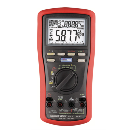
TRUE RMS DIGITAL INSULATION MULTIMETER
Pass /Fail Insulation Resistance Compare function;
12 selectable Preset Values.
LOCK-Test mode for Insulation Resistance &
Earth Continuity Test.
TM
BeepJack audible & visible input warning.
Remote Probe for insulation Resistance &
Earth Continuity Test.
+Hz
& VFD ACV : 7.0mA
with a duty cycle of 5 seconds on & 25 seconds off.
with a duty cycle of 5 seconds on and 25 seconds off.
: 0.25A/1KV, IR 30kA or better
: 1100Vrms
Magnetic hanger.
+Hz
range, 220mA @2.0
range.
All Specifications are subject to change without prior notice
MODEL KM 877
23 Functions 73 Ranges
Preliminary Data
Advertisement
Table of Contents

Related Manuals for Kusam-meco KM 877


Summary of Contents for Kusam-meco KM 877
- Page 1 & Others : 1000 Vrms ACCESSORIES : Test probe pair, BRP21S2-C Remote probe, Alligator clip pair, Holster, User manual & Carrying Case. OPTIONAL ACCESSORIES : Magnetic hanger. All Specifications are subject to change without prior notice D:/Chhaya/My Documents/Chhaya/backup/catlogs/NEW CAT/2013-2014/KM 877.cdr...
- Page 2 ELECTRICAL SPECIFICATIONS : KM 877 Accuracy is ± (% of reading digits + number of digits) or otherwise specified, at 23 C ± 5 C & less than 80%relative humidity. True RMS voltage & current accuracies are specified from 1 % to 100 % of range or otherwise specified.
- Page 3 ® USE TRUE RMS WHEN MEASURING AC WAVEFORMS The waveforms on today’s AC power lines are anything but clean. Electronic equipment such as office computers, with their switching power supplies, produce harmonics that distort power-line waveforms. These distortions make measuring AC voltage inaccurate when you use an averaging DMM.
- Page 4 ¬ Digital Sound Level Meter & Sound Level Calibrator ¬ Digital contact & Non-contact Type Tachometer ¬ Digital Non-contact (infrared) Thermometer ¬ Maximum Demand Controller/Digital Power Meter MODEL - KM 877 ¬ Digital Hand Held Temperature Indicators ® G 17, Bharat Industrial Estate, T. J. Road, Sewree (W), Mumbai - 400 015.
- Page 5 ® ® TRMS DIGITAL INSULATION MULTIMETER MODEL - KM 877...
-
Page 6: Table Of Contents
® ® TABLE OF CONTENTS I. SAFETY : This manual contains information and warnings that must be followed for operating the instrument safely and maintaining the TITLE PAGE NO. instrument in a safe operating condition. If the instrument is used in a manner not specified by the manufacturer, the protection provided by the instrument may be impaired. -
Page 7: Cenelec Directives
® ® The meter protection rating, against the users, is double insulation CAUTION : per IEC/UL/EN61010-1 Ed. 3.0, IEC/EN61010-2-030 Ed. 1.0, IEC/ Disconnect the test leads from the test points before changing EN61010-2-033 Ed. 1.0, IEC/UL/EN61010-031 Ed. 1.1 and CAN/ functions. -
Page 8: General Specifications
® ® IV. GENERAL SPECIFICATIONS : SAFETY : Safety : Double insulation per IEC/UL/EN61010-1 Display : 3-5/6 digits 6,000 counts Ed. 3.0, IEC/EN61010-2-030 Ed. 1.0, Polarity : Automatic Update Rate : 5 per second nominal IEC/EN61010-2-033 Ed. 1.0, IEC/UL/ 61 Segments Bar graph : 40 per second max EN61010-031 Ed. - Page 9 ® ® 1kHz ~ 3kHz Insulation Resistance @1mA test current : 6.000 V 50V output voltage : 25mA ±(2%rdg + 3dgts) 60.00 V 100V output voltage : 45mA 250V output voltage : 85mA 600.0 V 100 mV Unspecified 500V output voltage : 170mA 1000 V 1000V output voltage : 440mA 3kHz ~ 5kHz...
- Page 10 ® ® Insulation Resistance : Resistance : Range Accuracy Test Current Range Accuracy Test Voltage Resolution ±(0.9%rdg + 5dgts) 600.0 100 m 3.000M , 30.00M , 55.0M 1mA @50kW 100 V 3.000M , 30.00M , 110.0M 1mA @100kW 6.000 K ±(1.5%rdg + 5dgts) 250 V 3.000M , 30.00M , 275.0M...
-
Page 11: Product Description
® ® V. PRODUCT DESCRIPTION : VI. OPERATION : Note : Top of the line model is used as representative for illustration CAUTION : purposes. Please refer to your particular model for function Before and after hazardous voltage measurements, test the voltage availability. - Page 12 ® ® Diode Test Function W Resistance, Continuity Diode Test function is combined to its Rotary Knob Press the SELECT button momentarily to toggle the functions. Last position. selection will be saved as power up default for repeat measurement convenience. Continuity function is convenient for checking wiring connections &...
- Page 13 ® ® TEST Earth Continuity Test Function is active as long as the TEST button is pressed and hold. The TEST buttons on the meter & on the Remote Probe work This function measures the Resistance values of earth connection alike.
- Page 14 ® ® Insulation Resistance function : AUTO AUTO LOCK –––– –––– WARNING LOCK The LCD icons TEST used together throughout in this manual is ZERO LOCK ZERO LOCK SELECT RANGE COMPARE HOLD SELECT RANGE COMPARE HOLD referred as active measurements of Insulation Resistance TEST TEST PI/DAR...
- Page 15 ® ® NOTE. Maximum display reading of each Insulation Resistance 100V 250V –––– range is subjected to the test voltage selected. They are 55.0MW, –––– 0 I I 2 110.0MW, 275MW, 550MW & 25.0GW for 50V, 100V, 250V, 500V & 1000V respectively.
- Page 16 ® ® COMPARE mode flash flash This mode uses a preset insulation resistance threshold value for TEST TEST PASS FAIL PASS FAIL TEST TEST PASS/FAIL measuring comparison. The LCD annuciator PASS turns ZERO LOCK ZERO LOCK on when the TEST reading is higher than the selected threshold SELECT RANGE...
- Page 17 ® ® Then, activate Lock-Test mode LOCK & to start PI or DAR TEST Smooth mode (Insulation function only) : count-down measurements. The timer on the secondary display started Smooth mode displays the running average of the last eight to count down. The primary display shows the real-time resistance measured readings having changes within 300 counts in sequence.
-
Page 18: Maintenance
® ® Set Beeper Off : Press the RANGE button while turning the If the instrument voltage-resistance input terminal has subjected to high voltage transient (caused by lightning or switching surge to the meter on to temporarily disable the Beeper feature. Turn the rotary system) by accident or abnormal conditions of operation, the series switch OFF and then back on to resume. -
Page 19: Test Certificate
® MUMBAI WARRANTY Each “KUSAM-MECO” product is warranted to be free from defects in TEST CERTIFICATE material and workmanship under normal use & service. The warranty period is one year (12 months) and begins from the date of despatch of TRMS DIGITAL INSULATION MULTIMETER goods.
Need help?
Do you have a question about the KM 877 and is the answer not in the manual?
Questions and answers