Table of Contents
Advertisement
Quick Links
OTHER PRODUCTS
*
Digital Multimeter
Digital AC & AC/DC Clampmeter
*
AC Clamp Adaptor
*
*
AC/DC Current Adaptor
Transistorised Electronic Analog & Digital Insulation
*
Resistance Testers
*
Digital Sound Level Meter & Sound Level Calibrator
*
Digital contact & Non-contact Type Tachometer
*
Digital Non-contact (infrared) Thermometer
*
Thermo Hygrometer
*
Thermo Anemometer
*
Wood Moisture Meter
*
Distance Meter
*
Calibrators
*
Gas Analysers
*
Panel meters
*
Battery Testers
*
Digital Hand Held Temperature Indicators
*
Digital Lux Meter
*
Network Cable Tester
*
Power Factor Regulator
Maximum Demand Controller/Digital Power Meter
*
17, Bharat Industrial Estate, T. J. Road, Sewree (W), Mumbai - 400015. INDIA
Sales Direct: (022)24156638 Tel.:(022) 2412 4540, 2418 1649 Fax: 2414 9659
E-mail : kusam_meco@vsnl.net, Website : www.kusam-meco.co.in, www.kusamelectrical.com
DIGITAL MULTIMETER
KM 629
Advertisement
Table of Contents

Related Manuals for Kusam-meco KM 629


Summary of Contents for Kusam-meco KM 629
- Page 1 Network Cable Tester Power Factor Regulator Maximum Demand Controller/Digital Power Meter 17, Bharat Industrial Estate, T. J. Road, Sewree (W), Mumbai - 400015. INDIA Sales Direct: (022)24156638 Tel.:(022) 2412 4540, 2418 1649 Fax: 2414 9659 E-mail : kusam_meco@vsnl.net, Website : www.kusam-meco.co.in, www.kusamelectrical.com...
-
Page 2: Table Of Contents
1) SAFETY TABLE OF CONTENTS 1) SAFETY................This manual contains information and warnings that must 2) INTRODUCTION..............be followed for operating the instrument safely and 3) PRODUCT DESCRIPTION..........3-1) Panel IIIustration............maintaining the instrument in a safe operating condition. If 3-2) LCD IIIustration.......... - Page 3 WARNING LETTER AND COLOUR CODES FOR FUSES To avoid electrical shock hazard or damage to the meter, do Very quick acting : FF, or black; quick acting : F, or red; not exceed the overload protection shown in TABLE 1 medium time-lag: M, or yellow;...
-
Page 4: Introduction
WARNING CAUTION Disconnect the test leads from the test points before To reduce the risk of fire or electric shock, do not expose changing functions. Always set the instrument to the this product to rain or moisture. highest range and work downward for an unknown value if To avoid electrical shock hazard, observe the proper safety you are using manual ranging mode. -
Page 5: Product Description
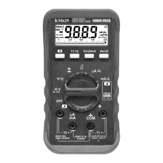
3) PRODUCT DESCRIPTION 3-1) Panel IIIustration 1. LCD display 4 digit 9999 counts LCD display 2. Rec Pushbutton. Push momentarily to activate Hold, or Press and Hold for 1 Hold second to activate RECORD function 3. %4-20mA Pushbutton. Push momentarily to activate Relative Zero, or Press and Hold for 1 second to activate %4-20mA industrial process control loop current... -
Page 6: 3-2) Lcd Iiiustration
3-3) Analog bar-graph 3-2) LCD IIIustration The analog bar graph provides a visual indication of Low Battery alert, replace the battery measurement like a traditional analog meter needle. It is as soon as possible to ensure excellent in detecting faulty contacts, indentifying accuracy potentiometer clicks, and indicating signal spikes during adjustments. -
Page 7: 3-4) Nmrr (Normal Mode Rejection Ratio)
3-4) NMRR (Normal Mode Rejection Ratio) 3-7) Average responding RMS calibrated NMRR is the DMM's ability to reject unwanted AC noise RMS (Root-Mean-Square) is the term used to describe effect which can cause inaccurate DC measurements. the effective or equivalent DC value of an AC signal. NMRR is typically specified in terms of dB (decibel). -
Page 8: 3-9) Harmonics Index (Hix)
4) Neutrals to overheat due to triplen harmonics Harmonics Index (HIX) function generates a comparative present on the neutral (150Hz or 180Hz) percentage index between 0% to 100% to indicate the 5) Bus bars and electrical panels to vibrate deviation of non-sinusoidal to sinusoidal waveform, which is a good indication of the presence of harmonics. -
Page 9: Operation
4) OPERATION b) Fundamental with 10% 3rd 4-1) DCV, ACV,Hz*, & HIX functions harmonics, y=100sin( t) + 1) Set rotary switch to position Hz HIX 10sin(3 t+ ) 2) Default at DC. Press Select button momentarily to c) Fundamental select AC, Hz, or HIX when required with 20% 3rd 3) Insert red ( ) test lead into... -
Page 10: 4-2) Temperature T1-T2 Function
(ACV) 4-2) Temperature T1-T2 function Set rotary switch to C F position Press Select button momentarily to toggle between C and F readings. Power up default can be set at C or F as power up option. See section Power up default C or F selection for more details Insert banana plug K-type temperature bead probe (optional accessory) with positive (+) plug into T1+ (+... -
Page 11: 4-3) Diode Test Function
4-3) Diode test function Set rotary switch to Insert red (+) test lead into + jack and black (-) test lead into COM input jack Connect the test leads as shown and observe the digital display Normal forward voltage drop (forward baised) for a good silicon diode is between 0.400V to 0.900V. -
Page 12: 4-4) Capacitance Function
4-4) Capacitance functions Set rotary switch to Default at diode. Press Select button momentarily to select capacitance Insert red (+) test lead into + jack and black (-) test lead into COM input jack Connect the test leads as shown and observe the digital display CAUTION Discharge capacitors before making any measurement. -
Page 13: 4-5) Resistance, ) ) Continuity Functions
4-5) Resistance, Continuity functions Set rotary switch to Insert red (+) test lead into + jack and black (-) test lead into COM input jack Connect the test leads as shown and observe the digital display Default at . Press Select button momentarily to select Continuity function A continuous beep tone indicates a complete wire. -
Page 14: 4-6) A, Ma, %4-20Ma Functions
4-6) A, mA, %4-20mA functions Set rotary switch to A or mA as required Insert red (+) test lead into A/mA jack and black (-) test lead into COM input jack Default at DC. Press Select button momentarily to select AC Connect the test leads as shown and observe the digital display In DC mA function, press and hold the %4-20mA (Rel... - Page 15 1-1) For gas or oil flames (Minipeeper): Low supply voltage Detector location Defective detector wiring Dirty viewing windows Faulty Minipeeper 1-2) For oil flames (Photocell): Detector location & wiring Smoky flame or poorly adjusted air shutter Faulty Photocell Temperature over 165 F (74 C) at photocell 1-3) For gas flames (Flame Rod): lgnition interference (A flame signal current difference with the ignition both on and off...
-
Page 16: A Function (Km629 Only)
4-7) function Temperature in excess of 600 F (316 C) at the 1) Set rotary switch to mA 2) Default at mA which will NOT auto-range to flame electrode insulator causing short to function. The user MUST press and hold the Select ground. -
Page 17: 4-9) Relative Mode
4-9) Relative mode Press the REL button momentarily to enter the Relative Zero ( ) mode, the LCD annunciator turns on. Relative zero allows the user to offset the meter measurements with a relative reference value. Practically all displaying readings can be set as relative reference value including MAX, MIN, MAX-MIN, and AVG readings of RECORD function. -
Page 18: 4-12) Line Filter Frequency 50 Hz Or 60 Hz Selection
largely surpasses competitors' single manual-ranging recording which is easily over-flowed, or with insufficient resolution. The meter features a fast single range sampling speed of 50ms for MAX, MIN, MAX-MIN and AVG readings. The faster the sampling speed, the more accurate the measurement of surges, spikes and sags will be. -
Page 19: 4-13) Power Up Default C Or F Selection
4-13) Power up default C or F selection Power up default C or F reading can be selected as a power-on option in a similar manner as describe in section (4-12). Press the Rel button while turning the meter on to display the set C or F. Press the Range button for C or press the Rel button for F selection. - Page 20 Dimension : (L)150mm X (W)75mm X( H)34mm (without Operating Temperature : 0 C to 35 C, 0-80% R.H.; 35 C holster); (L)160mm X (W)82mm X (H)48mm to 40 C, 0-70% R.H. (with holster) Storage Temperature : -20 C to 55 C, 0-80% R.H. (with Weight : approx.
- Page 21 DC Current AC Voltage Range Accuracy KM629 Range Accuracy KM629 40.00 A 0.25% + 3d 50Hz -- 200Hz 400.0 A 0.15% + 2d 999.9mV 2.5% + 8dgts 4.000mA 0.25% + 3d 50Hz -- 500Hz 40.00mA 0.05% + 3d 9.999V, 4.000A 0.5% + 4d 99.99V, 1.1% + 3d...
- Page 22 Frequency Ohms Range Accuracy Range Accuracy* KM629 9.999Hz, 99.99Hz, 999.9Hz, 9.999kHz, 0.05%+4d 999.9 0.5% + 5d 50.00kHz 9.999k , 0.5% + 2d 4 selectable trigger levels 1,2,3, and 4 (by Range button) 99.99k Input Signal : Sine wave, or Square wave with duty cycle 999.9k , 0.8% + 2d >40% &...
-
Page 23: Maintenance
6) MAINTENANCE WARNING To avoid electrical shock, remove test leads and any input signals before opening the case. Do not operate with open case. Install only the same type of fuse or equivalent 6-1) Battery replacement procedure When the battery symbol on the display is on, replace the battery as soon as possible to ensure accuracy. -
Page 24: 6-3) Cleaning And Storage
If the instrument voltage / resistance input terminal has subjected to high voltage transient (can be up to several KM 629 MODEL NO. ___________ thousand volts) by accident or abnormal conditions of operation, the series fusible resistors will be blown off SERIAL NO. -
Page 25: Warranty
WARRANTY THIS WARRANTY IS BUYER’S SOLE AND EXCLUSIVE Each “KUSAM-MECO” product is warranted to be free REMEDY AND IS IN LIEU OF ALL OTHER from defects in material and workmanship under normal WARRANTIES, EXPRESS OR IMPLIED, INCLUDING use & service.
Need help?
Do you have a question about the KM 629 and is the answer not in the manual?
Questions and answers