Table of Contents
Advertisement
Quick Links
Multi-point Digital Controller
MA900/MA901
Instruction Manual
Thank you for purchasing the RKC product. In order to achieve
maximum performance and ensure proper operation of your new
instrument, carefully read all the instructions in this manual.
Please place this manual in a convenient location for easy
reference.
SYMBOLS
: This mark indicates precautions that must be
WARNING
taken if there is danger of electric shock, fire, etc.,
which could result in loss of life or injury.
: This mark indicates that if these precautions and
CAUTION
operating procedures are not taken, damage to
the instrument may result.
!
: This mark indicates that all precautions should be
taken for safe usage.
: This mark indicates important information on
installation, handling and operating procedures.
: This mark indicates supplemental information on
installation, handling and operating procedures.
: This mark indicates where additional information
may be located.
!
!" An external protection device must be installed if
failure of this instrument could result in damage to
the instrument, equipment or injury to personnel.
!" All wiring must be completed before power is turned
on to prevent electric shock, fire or damage to
instrument and equipment.
!" This instrument must be used in accordance with the
specifications to prevent fire or damage to instrument
and equipment.
!" This instrument is not intended for use in locations
subject to flammable or explosive gases.
!" Do not touch high-voltage connections such as
power supply terminals, etc. to avoid electric shock.
!" RKC is not responsible if this instrument is repaired,
modified or disassembled by other than factory-
approved personnel. Malfunction can occur and
warranty is void under these conditions.
!" This is a Class A instrument. In a domestic environment, this
instrument may cause radio interference, in which case the
user may be required to take adequate measures.
!" This instrument is protected from electric shock by reinforced
insulation. Provide reinforced insulation between the wire for
the input signal and the wires for instrument power supply,
source of power and loads.
!" Be sure to provide an appropriate surge control circuit
respectively for the following:
− If input/output or signal lines within the building are longer
than 30 meters.
− If input/output or signal lines leave the building, regardless
the length.
All Rights Reserved, Copyright 2001, RKC INSTRUMENT INC.
IMR01H01-E4
WARNING
CAUTION
!" This instrument is designed for installation in an enclosed
instrumentation panel. All high-voltage connections such as
power
supply
instrumentation panel to avoid electric shock by operating
personnel.
!" All precautions described in this manual should be taken to
avoid damage to the instrument or equipment.
!" All wiring must be in accordance with local codes and
regulations.
!" All wiring must be completed before power is turned on to
prevent electric shock, instrument failure, or incorrect action.
The power must be turned off before repairing work for input
break and output failure including replacement of sensor,
contactor or SSR, and all wiring must be completed before
power is turned on again.
!" To prevent instrument damage or failure, protect the power line
and the input/output lines from high currents with a protection
device such as fuse, circuit breaker, etc.
!" Prevent metal fragments or lead wire scraps from falling inside
instrument case to avoid electric shock, fire or malfunction.
!" Tighten each terminal screw to the specified torque found in
the manual to avoid electric shock, fire or malfunction.
!" For proper operation of this instrument, provide adequate
ventilation for heat dispensation.
!" Do not connect wires to unused terminals as this will interfere
with proper operation of the instrument.
!" Turn off the power supply before cleaning the instrument.
!" Do not use a volatile solvent such as paint thinner to clean the
instrument. Deformation or discoloration will occur. Use a soft,
dry cloth to remove stains from the instrument.
!" To avoid damage to instrument display, do not rub with an
abrasive material or push front panel with a hard object.
!" Do not connect modular connectors to telephone line.
!" This manual assumes that the reader has a fundamental
knowledge of the principles of electricity, process control,
computer technology and communications.
!" The figures, diagrams and numeric values used in this manual
are only for purpose of illustration.
!" RKC is not responsible for any damage or injury that is caused
as a result of using this instrument, instrument failure or
indirect damage.
!" Periodic maintenance is required for safe and proper operation
of this instrument. Some components have a limited service life,
or characteristics that change over time.
!" Every effort has been made to ensure accuracy of all
information contained herein. RKC makes no warranty
expressed or implied, with respect to the accuracy of the
information. The information in this manual is subject to change
without prior notice.
!" No portion of this document may be reprinted, modified, copied,
transmitted, digitized, stored, processed or retrieved through
any mechanical, electronic, optical or other means without prior
written approval from RKC.
1. OUTLINE ・・・・・・・・・・・・・・・・・・・・・・・・・・・・・・・・・・・・・・・・ 1
2. MOUNTING ・・・・・・・・・・・・・・・・・・・・・・・・・・・・・・・・・・・・・ 3
3. WIRING ・・・・・・・・・・・・・・・・・・・・・・・・・・・・・・・・・・・・・・・・ 4
4. PARTS DESCRIPTION ・・・・・・・・・・・・・・・・・・・・・・・・・・・ 5
5. SETTING ・・・・・・・・・・・・・・・・・・・・・・・・・・・・・・・・・・・・・・・ 6
6. OPERATION ・・・・・・・・・・・・・・・・・・・・・・・・・・・・・・・・・・・ 14
7. FUNCTIONS ・・・・・・・・・・・・・・・・・・・・・・・・・・・・・・・・・・・ 16
8. ERROR DISPLAYS ・・・・・・・・・・・・・・・・・・・・・・・・・・・・・ 19
9. REMOVING THE INTERNAL ASSEMBLY ・・・・・・・・・・ 19
10. SPECIFICATIONS ・・・・・・・・・・・・・・・・・・・・・・・・・・・・・ 20
RKC INSTRUMENT INC.
®
terminals
must
be
enclosed
NOTICE
CONTENTS
in
the
Advertisement
Table of Contents

Related Manuals for RKC INSTRUMENT MA900


Summary of Contents for RKC INSTRUMENT MA900
- Page 1 !" RKC is not responsible for any damage or injury that is caused instrument and equipment. as a result of using this instrument, instrument failure or !"...
-
Page 2: Table Of Contents
1. OUTLINE As a multi-point digital controller of a DIN size 96 × 96 mm, there are MA900 of 4-channel type and MA901 of 8-channel type. This manual describes the specifications, setting, mounting and wiring. For the communication function, see the Communication Instruction Manual (IMR01H02-E# # # # ). - Page 3 Number of instruments (2≤n≤6) location: For mounting of the MA900/MA901, panel thickness must be between 1 to • Ambient temperature less than 0 °C or more than 50 °C. 10 mm. When mounting multiple MA900/MA901s close together, the panel •...
-
Page 4: Ma900 (Ma901)
Recommended fuse rating: Rated voltage 250 V, Rated current 1 A Fuse type: Time-lag fuse #" Use the solderless terminal appropriate to the screw size. Screw size: M3×6 Recommended tightening torque: 0.4 N・m (4 kgf・cm) 3.2 Terminal Configuration !" MA900 3, 4 (6) Contact input (8) CT input (9) Input (5) Alarm output... -
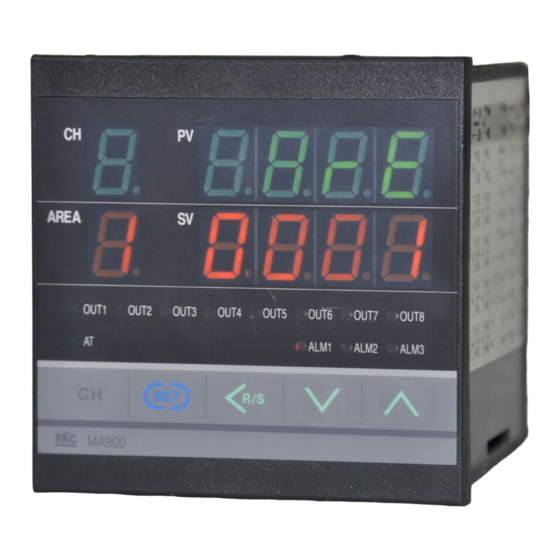
Page 5: V: Voltage Pulse Output
ALM1: Lights when alarm1 is turned on. Shift & R/S key ALM2: Lights when alarm2 is turned on. (The above figure is MA900. The figure of ALM3: Lights when alarm3 is turned on. he avoid damage to the instrument, MA901 is the same as a MA900.) -
Page 6: Alarm
5. SETTING This chapter describes the operation flowchart of mode and the setting item of each mode. This instrument classes setting item in four kinds of mode. The mode can be selected by pressing the SET or <R/S key. 5.1 Operation Flowchart of Mode •... - Page 7 • Displays the input value of the current transformer 1 used when the instrument is provided with the heater break alarm 2 (Z-168). Current transformer 2 monitor [ Correspond to only MA900] Displays the input value of the current transformer 2 used when the instrument is provided with the heater break alarm 2 (Z-168).
- Page 8 Heater break alarm 2 (HBA2) [Correspond to only MA900] HBA2 set value is set by referring to monitor value from the current transformer 2. Used only for three- phase. Displayed only for when the heater break alarm (Z-168) is selected as alarm 2.
- Page 9 Continued from the previous page. Cool-side proportional cycle time [Correspond to only MA900] Displayed only for heat/cool PID control. Set the cool-side control output cycle for the heat/cool PID control. Setting range: 1 to 100 seconds AREA Factory set value: Relay contact output 20 seconds Voltage pulse output, triac output 2 seconds •...
-
Page 10: A: Deviation High Alarm
5.5 Parameter Setting Mode The parameter setting mode is used to set various settings relating to control, to change various alarm settings and also to set the setting change rate limiter and used/unused channels. Setting items belonging to the parameter setting mode correspond to the multi-memory area functions and can be stored up to eight memories. - Page 11 Factory set value: 100 % No setting can be changed when “1 (Lock)” is selected by the lock level 1. Cool-side proportional band [Correspond to only MA900] Displayed only for heat/cool PID control. Set the cool-side proportional band for the heat/cool PID control.
-
Page 12: Setting Procedure
5.6 Setting Procedure 5.6.1 Usual setting (Setting for each channel) Some examples of changing the set value (SV) are described in the following. The same setting procedure applies when other parameters are also set. !" When the SV is changed !"... - Page 13 5.6.2 Batch setting (All channels batch setting) The parameters selected from one memory area and corresponding to all of the channels can be simultaneously set as the same value. The set values (SV) as well as the parameters set for each channel can be simultaneously set. Some examples of changing the set value (SV) simultaneously are described in the following.
- Page 14 6. OPERATION This chapter describes instrument operation, the instrument operation, RUN/STOP transfer, and control area transfer, etc. 6.1 Power ON When the contact input state is RUN mode, After power on, this instrument starts control in about 4 seconds. RUN/STOP can be selected by key operation. : Only key operation is in the STOP mode.
- Page 15 6.4 Transfer of Control Area 6.5 Autotuning (AT) The memory area used for this control (control area) can be The AT function automatically measures, computes and sets the selected by contact input (option) or communication (option) optimum PID and LBA constants. If the AT function is activated, other than the key operation.
- Page 16 7. FUNCTIONS This chapter describes an outline of function of MA900/MA901. 7.1 PV Bias Function 7.5 Scan Display Function The value set in the PV bias is added to the input value (actual The scan display function is for automatically selecting the measured value) to correct the input value.
-
Page 17: G: Deviation High/Low Alarm
"# 7.6 Batch Setting Function Alarm differential gap If measured value (PV) is close to the alarm set value, the alarm The batch setting function enables the setting of the parameters relay contact may repeatedly turn on and off due to input selected within one memory area simultaneously to the same fluctuations. - Page 18 LBD. [Corresponding to MA900] When the measured value (PV) is within the LBD area, no alarm is produced even if all of the conditions to produce the alarm are...
- Page 19 EEPROM error internal assembly. Alarm output: again, please contact RKC sales All the output is #" To prevent electrical shock or instrument failure, always office or the agent. OFF. A/D conversion turn off the power before pulling out the internal assembly.
-
Page 20: K: Process High Alarm
!" !" !" !" !" Input Alarm function Number of inputs: MA900: 4 channels MA901: 8 channels Number of points: 3 points (Option: 2 points) Thermocouple: Isolated between each input channel Alarm type: Specify when ordering RTD, Voltage: Not isolated between each input channel... - Page 21 !" !" !" !" Input range table #Thermocouple input and RTD input #Thermocouple input and RTD input Type Range Code Type Range Code 0.0 to 350.0 °C 0 to 200 °C -199.9 to +752.0 °F 0 to 400 °C -100.0 to +200.0 °F 0 to 600 °C 0 to 800 °C -100.0 to +400.0 °F...
- Page 22 Used/unused of channels The first edition: APR.2001 The fourth edition: JUL.2002 [IMQ00] HEADQUARTERS: 16-6, KUGAHARA 5-CHOME, OHTA-KU TOKYO 146-8515 JAPAN PHONE:03-3751-9799 (+81 3 3751 9799) E-mail: info@rkcinst.co.jp RKC INSTRUMENT INC. ® FAX: 03-3751-8585 (+81 3 3751 8585) JUL. 2002 IMR01H01-E4...
Need help?
Do you have a question about the MA900 and is the answer not in the manual?
Questions and answers