Advertisement
Quick Links
Ramp/Soak Controller
Quick Operation
PF900/PF901
Manual
All Rights Reserved, Copyright 2009, RKC INSTRUMENT INC.
This manual describes the basic key operation and mode selection of the PF900/PF901.
For detailed handling procedures and various function settings, please refer to the following
separate manuals:
• PF900/PF901 Instruction Manual (IMR02L03-E )
The above manuals can be download from our website:
URL: http://www.rkcinst.com/english/manual_load.htm
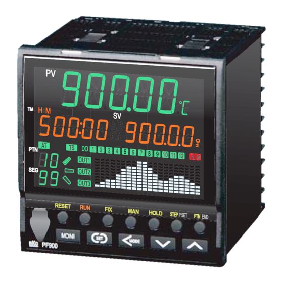
1. PARTS DESCRIPTION
(1)
††††‡
PV
(2)
(15)
‰
(3)
(16)
TM
H:M:S
SV
‡
(4)
!
(17)
AT
TS
DO
1
2 3 4 5 6 7 8 9 10 11 12 ALM
(5)
8 8
PTN
OUT1
(18)
8 8
OUT2
SEG
(6)
OUT3
(19)
(7)
RESET
RUN
FIX
MAN
HOLD STEP R.SET PTN END
(20)
(8)
MONI
SET
MODE
(21)
PF900
(9)
(10)
(11)
(12)
(13)
(14)
(1) Measured value (PV)
Displays measured value (PV) or various parameter symbols.
display
[Green *]
(2) TIME display
Displays selected time unit: Hour and Minute (H: M) or Minute
[Orange *]
and Second (M: S).
(3) SV/Timer display
Displays Set value (SV), Timer setting time or various
[Orange *]
characters.
(4) AT/TS lamp [Green *] AT: Flashes when autotuning is activated.
(After autotuning is completed: AT lamp will go out)
TS: Lights when time signal is turned on.
(5) PTN display [Green *] Displays the pattern number in the execution: 1 to 99.
(6) SEG display [Green *] Displays the segment number in the execution: 1 to 99.
(7) Gradient state lamp
Displays the state of program in process: rise, soak and fall.
The display flashes when the process is in the wait mode.
[Green *]
(8) Output lamp [Green *] Lights when the output (OUT1 to OUT3) corresponding to
each lamp is ON.
Lamp indication becomes as follows for current output and
voltage current.
For an output of less than 0 %:
Extinguished
For an output of more than 0 %: Lit
(9) Loader
Setting and monitoring on a personal computer (PC) is
communication
possible if the controller is connected with our cable to a PC
connector
via our USB communication converter COM-K-3 (sold
1
separately)
.
2
Our communication software
must be installed on the PC.
(10)
Use to switch the monitor screen. Pressing this key while any
Monitor key
screen other than the SV setting & Monitor mode screen is
being displayed returns to the Measured value (PV)/Set value
(SV) monitor screen.
(11)
Used for parameter calling up and set value registration.
Set key
(12)
Shift digits when settings are changed. Used to selection
Shift key
operation between modes.
(13)
Decrease numerals.
DOWN key
To scroll through numbers faster, press and hold the DOWN
key in the manual mode.
To turn back to the previous time of the program, press and
hold the DOWN key in the operation mode.
(14)
Increase numerals.
UP key
To scroll through numbers faster, press and hold the UP key
in the manual mode.
To forward the time of the program, press and hold the UP
key in the operation mode.
(15) Unit display [Green*] Displays unit: °C (°F) or %
Lights % for parameters in unit of %.
(16) Set lock display
Lights when the settings are locked.
[Orange*]
(17) ALM lamp
[Red] Lights when alarm (Event or heater break alarm [HBA]) is
turned ON.
Confirm the alarm type at the Event monitor display.
(18) Digital output lamp
Lights when the digital output (DO1 to DO12) corresponding
[Green*]
to each lamp is ON.
(19) Program pattern/
Displays program patterns or bar graph for manipulated value
Bar graph display
(MV). Red display is selectable at event or self-diagnostic
[White]
error.
*
PF901: White
1
For the COM-K, refer to COM-K Instruction Manual (IMR01Z01-E□).
2
Software name: WinUCI-PF900 (Only available as a download from our website.)
(20) State display lamp
RESET: Lights in RESET mode [Orange] **
[Green or Orange]
RUN:
Lights in RUN mode [Orange] **
FIX:
Lights in FIX mode [Orange] **
MAN:
Lights in MAN mode [Orange] **
** Other lamps light in green.
HOLD: Lights when the HOLD key is valid. [Green]
IMR02L02-E2
STEP: Lights when the STEP/R.SET key is set to STEP
[Green]
R.SET: Lights when the STEP/R.SET key is set to R.SET
[Green]
PTN:
Lights when the PTN/END key is set to PTN [Green]
END:
Lights when the PTN/END key is set to END [Green]
(21)
Direct key
RESET: Use to switch to RESET (Control stop) mode.
RUN:
Use to switch to RUN (Program control start) mode.
FIX:
Use to switch to FIX (Fixed set point control) mode.
MAN:
Use to switch to MAN (Manual control) mode.
HOLD: Use to stop the process of the program or release the
hold function.
STEP/R.SET
STEP: Use to forward a segment of the program.
R.SET: Use to turn back to the previous parameter setting.
PTN/END
PTN:
Use to display the execution pattern setting display.
END:
Use to set or release the Program end when setting
program.
2. PARAMETER SETTING MODE
2.1 Transfer to Each Mode
The controller has five different setting modes, and all settable parameters belongs to one of
them. The following chart show how to access different setting mode.
Power ON
Input type/Input range display
Automatically (in 4 seconds)
Press the
key while
pressing the
key for
2 seconds or more
SV setting & Monitor mode
• Mode to be selected during
normal operation
• Changes SV, TIME, etc
• Monitor PV, SV, MV, etc
Press the
key
Press and hold the
while pressing
key for 2 seconds
or more
the
key
Parameter setting mode
Create program pattern, set the
parameters such as PID and
Event, or set the parameters for
program setting such as the
time signal.
Press and hold the
key for 2 seconds or more
Setup setting mode
In this mode, it is possible to
set setting items not stored in
the Parameter setting mode.
Some parameters are also
settable in the Engineering
mode.
Press the
key while
pressing the
key for
2 seconds or more
Engineering mode
The content relating to the
specification of this product is
set. Set meet application
requirements. For details, refer
to PF900/PF901 Instruction
Manual (IMR02L03-E ).
Initial level engineering
mode
For details, refer to
PF900/PF901 Instruction
Manual (IMR02L03-E ).
Press the
key or
Press the
key while pressing the
key
Input type and range display
This instrument immediately displays input type symbol and input range following power ON.
Example: When sensor type is K thermocouple (−200 to +1372 °C)
Power ON
Symbol
Automatically
InP
(in 2 seconds)
@$ K
Unit for input display
Input type symbol:
TC/RTD input:
Symbol
°C or °F
Voltage/Current input:
Input type
No display
Symbol
Input type
2.2 Parameter Selection within Mode
SV setting & Monitor mode
It is possible to set SV which is a control target and also to monitor PV, SV, MV, etc.
Program mode
In PV/SV monitor, press the
key. The
display goes to the segment level/time setting.
PV/SV monitor
28
000: 00 00000
LEVEL
Segment level
[Factory set value: 0]
000: 00 000000
Press and hold the
key
TIME
Segment time
for 2 seconds or more
[Factory set value: 0:00]
000: 00 00000
Fix mode *
Operation mode
In PV/SV monitor, press the
key. The
Change operation status/
display goes to the set value setting.
mode such as Program/
PV/SV monitor
FIX/Manual/RESET and
28
PID/AT, etc.
0
SV
Set value
Press the
key while
[Factory set value: 0]
pressing the
key for
00000
2 seconds or more
Manual mode
The
key and
key is used to
manipulate output setting in Manual mode.
PV/SV monitor
28
MV
0.0
Executing pattern setting
In PV/SV monitor, press the PTN/END key.
The display goes to the executing pattern
setting.
PV/SV monitor
28
000: 00 00000
Parameters in Engineering
Press the PTN/END key
mode are settable only when
the controller is in RESET
PTN
mode. However, it is possible
to check only the data even
00001
in RUN mode.
*
Fix mode: Fixed set point control mode
For details of the SV setting & Monitor mode, refer to the
PF900/PF901 Instruction Manual (IMR02L03E- ).
Parameter setting mode
It is possible to set any parameter relating to control.
PV/SV monitor
28
PV/SV monitor
000: 00 00000
Automatically
RANGE
28
(in 2 seconds)
-200 1372
0:00
0
Program
Input range high
setting block
Input range low
PROG
K J T S R E b n
P
W
TC
K
J
T S R E B N
PLⅡ W5ReW26Re
Program memory
group setting
U L
PR
PT
JP
V
I
block
TC
RTD
Voltage Current
PR.MEM
U L
PR40-20
Pt100
JPt100
V
mA
PID memory
group setting
block
PID
Monitor mode
Press the
key can be change the
monitor displays.
Event memory
PV/SV monitor
group setting
block
28
EVENT
000: 00 00000
28
Pattern remaining time
Wait memory
monitor
group setting
PTN.TM 0: 00
block
WAIT
28
Segment repeat
remaining time/
RPT. SG
0
execution time monitor
Time signal
memory group
28
Pattern repeat time/
setting block
execution time monitor
RPT. PN
0
TM.SIG
28
Total pattern repeat
remaining time/
RPT. PR
0
Output program
execution time monitor
memory group
setting block
PRO.MV
28
Wait condition monitor
WAIT
OOO
Level PID
28
Event state monitor
setting block
LV.PID
EV
ooooooo
28
Time signal state
monitor
Reset mode
TS oooooooo
setting block
RESET
28
Current transformer 1
(CT1) input value
CT1
0
monitor
Fix mode
setting block
FIX
28
Current transformer 2
(CT2) input value
CT2
0
monitor
Manual control
28
Manipulated output
mode setting
value 1 (MV1) monitor
MV1
0. 0
block
MAN
28
Manipulated output
value 2 (MV2) monitor
MV2
0. 0
Edit block
EDIT
*
Fix mode: Fixed set point control mode
For details of the Parameter setting mode, refer to the
PF900/PF901 Instruction Manual (IMR02L03E- ).
(2 seconds or more)
Setting pattern
Output program
number
memory group number
PTN.NO
P.MV.GR
01
00000
Setting pattern
number
Segment signal
PTN.NO
SIGNL
00001
00000
PID memory group
number
LBD deadband
PID.GR
LBD
00001
GR. 1
00000
Event 4 set value
Event memory group
(EV4) [low]
number
EV.GR
EV4`
00001
GR. 1
-0050
Wait memory group
number
Wait time-out set value
WT.GR
TM.OUT
00001
GR. 1
000: 00
Time signal memory
group number
Time signal end time
TS.GR
01.E.TM
00001
GR. 1
000: 00
Output program memory
Output program value 3
group number
P.MV.GR
P.MV3
00001
GR. 1
-005. 0
Level PID setting 1
Level PID setting 7
LEVL.1
LEVL.7
PID
00000
PID
00000
Set value (SV) in
Event memory group
Reset mode
number in Reset mode
SV
EV.GR
RESET 00000
RESET 00001
*
Set value (SV) in
Event memory group
Fix mode
*
number in Fix mode
*
SV
EV.GR
FIX
00000
FIX
00001
PID memory group number
Event memory group number
in Manual control mode
in Manual control mode
PID.GR
EV.GR
MAN
00001
MAN
00001
Pattern copy
Data clear
COPY
CLR
00 ‹ 00
00000
Advertisement

Subscribe to Our Youtube Channel
Related Manuals for RKC INSTRUMENT PF900


Summary of Contents for RKC INSTRUMENT PF900
- Page 1 PF900/PF901 Instruction Manual (IMR02L03E- ). STEP: Lights when the STEP/R.SET key is set to STEP RANGE (in 2 seconds) (in 2 seconds) This manual describes the basic key operation and mode selection of the PF900/PF901. [Green] (2 seconds or more) @$ K -200 1372 0:00 R.SET: Lights when the STEP/R.SET key is set to R.SET...
- Page 2 PID values may also be necessary if the set value is around the ambient temperature or PV/SV monitor PF900/PF901 Instruction Manual (IMR02L03E- ). Conforms to the setting of Event output action at input error in the Engineering mode PROG PTN.NO...
Need help?
Do you have a question about the PF900 and is the answer not in the manual?
Questions and answers