
Related Manuals for RKC INSTRUMENT REX - C100


Summary of Contents for RKC INSTRUMENT REX - C100
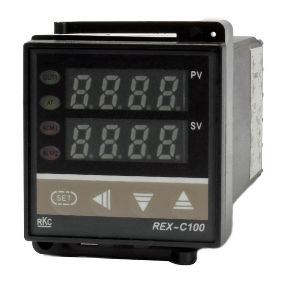
- Page 1 REX - C100 REX - C700 REX - C400 REX - C900 REX - C410 INITIAL SETTING MANUAL C RKC INSTRUMENT INC. RANKLIN H. (07) 3391 4865...
-
Page 2: Table Of Contents
This is a manual for the initial setting of the REX-C100, -C400, -C410, -C700, & -C900. Do not touch or adjust parts other than those covered in this manual. The instrument was manufactured and delivered under close quality control by us. However, is some subject troubled or noted, your kindly announce and advice to our business department, nearest business office also agent where you bought is very much appreciated. -
Page 3: Initial Set Mode Changing
I n i t i a l s e t m o d e c h a n g i n g Entering the initial set mode Press the key to display the set data locking parameter symbol on the measured-value (PV) display unit. At this time, the least significant digit on the set-value (SV) display unit lights brightly. -
Page 4: Exiting The Initial Set Mode
Exiting the initial set mode Exits from the initial set mode Keep pressing both the key (A) and (B) keys simultaneously for more than 5 seconds can enter the PV/SV display mode. ‰ Even if the controller exits from the initial set mode at any point, the setting mode so far set becomes valid. Locks the initial set mode (Change the content of set data lock setting) Press the key to enter the parameter setting mode. -
Page 5: Setting
S e t t i n g Description of each parameter “ ” appears on the display, and every press of the key advances the parameter symbol as shown in the following table. After one cycle, the display shows “ ”. -
Page 6: Each Parameter Setting
Each parameter setting Method of setting Press the key to display the input type selection parameter symbol ( ) on the measured-value (PV) display unit. At this time, the least significant digit on the set-value (SV) display unit lights brightly. The digit which lights brightly is settable. -
Page 7: Input Type Selection
Input type selection ( Set-value (SV) display unit VALUE INPUT TYPE HARDWARE W5Re / W26Re PLII Pt100 S (JIS / IEC) J Pt100 S (JIS) 0 to 5 V DC Voltage 1 to 5 V DC 0 to 20 mA DC Current 4 to 20 mA DC Cautions... -
Page 8: Engineering Unit And Cooling Type Selection
Engineering unit and cooling type selection ( Set-value (SV) display unit VALUE DESCRIPTION Engineering unit selection ‰ 1 Air-cooling (Type A) Cooling type ‰ 2 Water-cooling (Type W) selection Fixed ‰ 1 Type A : Heating / cooling PID action (Air-cooling) ‰... -
Page 9: Selection Of Break Alarm (Hba, Lba) Etc
Selection of break alarm (HBA, LBA) etc. ( Set-value (SV) display unit VALUE DESCRIPTION Without HBA function Heater break alarm (HBA) With HBA function selection Without LBA function Control loop break alarm With LBA function (LBA) selection Without Z-132 specification Special specification ‰... -
Page 10: First Alarm (Alm1) Type Selection
First-alarm (ALM1) type selection ( Set-value (SV) display unit VALUE DESCRIPTION No first alarm High alarm Low alarm Deviation First alarm (ALM1) High / Low alarm alarm type selection Band alarm (See page 10) High alarm Process Low alarm alarm Without alarm hold action First alarm (ALM1) With alarm hold action... -
Page 11: Second Alarm (Alm2) Type Selection
Second-alarm (ALM2) type selection ( Set-value (SV) display unit VALUE DESCRIPTION No second alarm High alarm Low alarm Deviation Second alarm (ALM2) High / Low alarm alarm type selection Band alarm (See page 10) High alarm Process Low alarm alarm Without alarm hold action Second alarm (ALM2) With alarm hold action... - Page 12 A L A R M T Y P E S Î : Alarm set-value [ g : Set-value (SV) : Alarm status (ALM1 or ALM2 LED lighting) ] < D E V I A T I O N A L A R M >...
-
Page 13: Control Output Selection Etc
Control-output selection etc. ( Set-value (SV) display unit VALUE DESCRIPTION Direct action (Type D) Direct / reverse action Reverse action (Type F, A, W) selection ‰ 1 PID action (Type D, F) Control action Heating / cooling PID action (Type A, W) ‰ 1 type selection Time proportional output (M, V, G output) ‰... -
Page 14: Energize/De-Energize Alarm Selection Etc
Energize / de-energize alarm selection etc. ( Set-value (SV) display unit VALUE DESCRIPTION Energize alarm Energize / de-energize alarm selection De-energize alarm (First alarm side) Energize alarm Energize / de-energize alarm selection De-energize alarm (Second alarm side) Without Z-124 specification Special specification [Z-124] selection ‰... -
Page 15: Pv Bias Setting
PV bias setting ( Set-value (SV) display unit (Setting range) TC and RTD inputs For a resolution of 1EC [EF] -1999 to 9999EC [EF] For a resolution of 0.1EC [EF] : -199.9 to +999.9EC [EF] Voltage and current inputs -199.9 to +200.0% Differential gap setting of ON / OFF action [ Set-value (SV) display unit (Setting range) -
Page 16: High-Limit Setting For Set-Value (Sv)
(12) High-limit setting for set-value (SV) [ Set-value (SV) display unit INPUT TYPE RANGE 0 to 1372EC 0 to 2502EF 0 to 1200EC 0 to 2192EF 0 to 800EC 0 to 1600EF 0 to 1000EC 0 to 1832EF 0 to 1300EC 0 to 2372EF R, S 0 to 1769EC... -
Page 17: Each Parameter Checks
E a c h P a r a m e t e r c h e c k s When all the settings are finished, press the key to check each parameter. When the contents of the initial setting are changed, change the model code plate stuck to inside of the controller and outside of the case by referring to the following table. - Page 18 I N P U T R A N G E T A B L E INPUT TYPE INPUT RANGE MODEL CODE INPUT TYPE INPUT RANGE MODEL CODE 0 to 200EC 0 to 400EC 0 to 1300EC 0 to 600EC PLII 0 to 1390EC 0 to 800EC (NBS)
Need help?
Do you have a question about the REX - C100 and is the answer not in the manual?
Questions and answers
Заказывал контроллер с предустановкой производителя 0 - 1300 градусов. Получил с предустановка производителя 0 - 400 градусов цельсия. Как использовать с датчиком 0 - 1000 градусов?
Can you set it back to factory settings?
Как отключить пид настройки