Table of Contents
Advertisement
Quick Links
Limit Controller
SA100L Instruction Manual
Thank you for purchasing this RKC product. In order to achieve maximum performance
and ensure proper operation of your new instrument, carefully read all the instructions in
this manual. Please place the manual in a convenient location for easy reference.
!
To prevent injury to persons, damage to instrument and
equipment, a suitable external protection device shall be required.
All wiring must be completed before power is turned on to prevent
electric shock, fire or damage to instrument and equipment.
This instrument must be used in accordance with the specifications
to prevent fire or damage to instrument and equipment.
This instrument is not intended for use in locations subject to
flammable or explosive gases.
Do not touch high-voltage connections such as power supply
terminals, etc. to avoid electric shock.
RKC is not responsible if this instrument is repaired, modified or
disassembled
by
other
Malfunction can occur and warranty is void under these conditions.
CAUTION
This product is intended for use with industrial machines, test and
measuring equipment. (It is not designed for use with medical
equipment and nuclear energy.)
This is a Class A instrument. In a domestic environment, this instrument
may cause radio interference, in which case the user may be required
to take additional measures.
This instrument is protected from electric shock by reinforced insulation.
Provide reinforced insulation between the wire for the input signal and
the wires for instrument power supply, source of power and loads.
Be sure to provide an appropriate surge control circuit respectively for
the following:
- If input/output or signal lines within the building are longer than 30 meters.
- If input/output or signal lines leave the building, regardless the length.
This instrument is designed for installation in an enclosed
instrumentation panel. All high-voltage connections such as power
supply terminals must be enclosed in the instrumentation panel to avoid
electric shock by operating personnel.
All precautions described in this manual should be taken to avoid
damage to the instrument or equipment.
All wiring must be in accordance with local codes and regulations.
All wiring must be completed before power is turned on to prevent
electric shock, instrument failure, or incorrect action. The power must
be turned off before repairing work for input break and output failure
including replacement of sensor, contactor or SSR, and all wiring must
be completed before power is turned on again.
To prevent instrument damage as a result of failure, protect the power
line and the input/output lines from high currents with a suitable
overcurrent protection device with adequate breaking capacity such as
a fuse, circuit breaker, etc.
Prevent metal fragments or lead wire scraps from falling inside
instrument case to avoid electric shock, fire or malfunction.
Tighten each terminal screw to the specified torque found in the manual
to avoid electric shock, fire or malfunction.
For proper operation of this instrument, provide adequate ventilation for
heat dispensation.
Do not connect wires to unused terminals as this will interfere with
proper operation of the instrument.
Turn off the power supply before cleaning the instrument.
Do not use a volatile solvent such as paint thinner to clean the
instrument. Deformation or discoloration will occur. Use a soft, dry cloth
to remove stains from the instrument.
To avoid damage to instrument display, do not rub with an abrasive
material or push front panel with a hard object.
When high alarm with hold action/re-hold action is used for Alarm
function, alarm does not turn on while hold action is in operation. Take
measures to prevent overheating which may occur if the control device
fails.
NOTICE
This manual assumes that the reader has a fundamental knowledge of
the principles of electricity, process control, computer technology and
communications.
The figures, diagrams and numeric values used in this manual are only
for purpose of illustration.
RKC is not responsible for any damage or injury that is caused as a result
of using this instrument, instrument failure or indirect damage.
RKC is not responsible for any damage and/or injury resulting from the
use of instruments made by imitating this instrument.
Periodic maintenance is required for safe and proper operation of this
instrument. Some components have a limited service life, or
characteristics that change over time.
Every effort has been made to ensure accuracy of all information
contained herein. RKC makes no warranty expressed or implied, with
respect to the accuracy of the information. The information in this
manual is subject to change without prior notice.
No portion of this document may be reprinted, modified, copied,
transmitted, digitized, stored, processed or retrieved through any
mechanical, electronic, optical or other means without prior written
approval from RKC.
All Rights Reserved, Copyright 2004, RKC INSTRUMENT INC.
IMR01J07-E2
WARNING
than
factory-approved
personnel.
®
1. PRODUCT CHECK
SA100L
(1)
(2)
(1) Type
L: Limit controller
(2) Input type/Range code
Refer to 11. INPUT RANGE TABLES (P. 10)
(3) Output 1 (Limit output or Transmission output)
M: Relay contact output
8: Current output (4 to 20 mA DC)
(4) Output 2 (Limit output or Alarm output)
N: No output
When the output 1 is "7" or "8," output 2 is fixed to "M."
(5) Power supply voltage
3: 24 V AC/DC
(6) Alarm 1 and (7) Alarm 2
N: No alarm
A: Deviation high alarm
B: Deviation low alarm
C: Deviation high/low alarm
D: Band alarm
E: Deviation high alarm
F: Deviation low alarm
(8) Optional function
N: No function
5: RS-485 (RKC communication) 6: RS-485 (Modbus)
(9) Waterproof/Dustproof
N: No Waterproof/Dustproof
(10) Output assignment code
No symbol: Standard output
When the OUT1 is relay contact output;
OUT1: Limit output
OUT2: OR output of alarm 1 and alarm 2
When the OUT1 is current output;
OUT1: Transmission output
OUT2: Limit output
02: OUT1: Limit output
03: OUT1: Limit output
04: OUT1: Limit output
05: OUT1: Limit output
06: OUT1: Limit output
07: OUT1: Limit output
08: OUT1: Limit output
09: OUT1: Limit output
10: OUT1: Limit output
11: OUT1: Limit output
12: OUT1: Limit output
13: OUT1: Limit output
14: OUT1: Limit output
16: OUT1: Transmission output, OUT2: Limit output
1
With hold action
(11) Version symbol
No code: For Japanese domestic market
2. MOUNTING
To prevent electric shock or instrument failure, always turn
To prevent electric shock or instrument failure, always turn
off the power before mounting or removing the instrument.
off the power before mounting or removing the instrument.
2.1 Mounting Cautions
(1) This instrument is intended to be used under the following environmental
conditions. ( IEC61010-1 )
[OVERVOLTAGE CATEGORY II, POLLUTION DEGREE 2]
(2) Use this instrument within the following environment conditions:
Allowable ambient temperature: 0 to 50 C
Allowable ambient humidity:
(Absolute humidity: MAX. W. C 29.3 g/m
Installation environment conditions: Indoor use, Altitude up to 2000 m
(3) Avoid the following when selecting the mounting location:
Rapid changes in ambient temperature which may cause condensation.
Corrosive or inflammable gases.
Direct vibration or shock to the mainframe.
Water, oil, chemicals, vapor or steam splashes.
Excessive dust, salt or iron particles.
Excessive induction noise, static electricity, magnetic fields or noise.
Direct air flow from an air conditioner.
Exposure to direct sunlight.
Excessive heat accumulation.
RKC INSTRUMENT INC.
(3) (4)
(5)
(6) (7)
(8) (9) (10) (11)
7: Current output (0 to 20 mA DC)
M: Relay contact output
4: 100 to 240 V AC
G: Deviation high/low alarm
H: Process high alarm
J: Process low alarm
K: Process high alarm
L: Process low alarm
1
V: SV high alarm
1
W: SV low alarm
D: Contact input
1: Waterproof/Dustproof
2
or
2
2
, OUT2: AND output of alarm 1 and alarm 2
2
3
, OUT2: Alarm 1 output
2
, OUT2: OR output of alarm 1 and alarm 2
2
, OUT2: AND output of alarm 1 and alarm 2
2
2
, OUT2: Alarm 1 output
2
, OUT2: OFF
3
, OUT2: OR output of alarm 1 and alarm 2
3
, OUT2: AND output of alarm 1 and alarm 2
3
3
, OUT2: Alarm 1 output
3
, OUT2: OR output of alarm 1 and alarm 2
3
, OUT2: AND output of alarm 1 and alarm 2
3
2
, OUT2: Alarm 1 output
3
, OUT2: OFF
3
2
3
De-energized
Energized
/Y: For International market
WARNING
!
5 to 95 %RH
3
dry air at 101.3 kPa)
Continued on the next page.
/
/
Y
1
1
1
3
3
2
2
3
3
2
2
Advertisement
Table of Contents

Related Manuals for RKC INSTRUMENT SA100L


Summary of Contents for RKC INSTRUMENT SA100L
- Page 1 Exposure to direct sunlight. mechanical, electronic, optical or other means without prior written Excessive heat accumulation. approval from RKC. Continued on the next page. All Rights Reserved, Copyright 2004, RKC INSTRUMENT INC. RKC INSTRUMENT INC. ®...
- Page 2 To prevent electric shock or instrument failure, do not turn visual field range. The visual on the power until all wiring is completed. Make sure that field range of SA100L is 40 the wiring is correct before applying power to the to the upper side, and 30 to instrument.
-
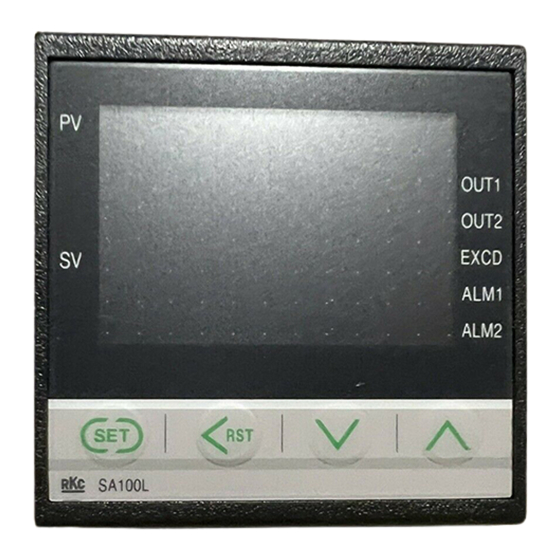
Page 3: Parts Description
EXCD (1) Set value (SV) ALM1 NO: Normally Open display ALM2 NC: Normally Close Input terminals SA100L (7) SET key (4) UP key (6) <RST key (5) DOWN key Power terminals (1) Set value (SV) display [Red]... - Page 4 5. SETTING Power ON If the key is not pressed for more than one minute, the display will automatically return to Input Type/Input Range Display the SV Setting & Monitor Mode. (Display for approx. 4 seconds) Display changes SET <RST key Communication Setting Mode SET key (2 seconds) automatically...
-
Page 5: Operation
Changing Parameter Settings 6.1 Operation Procedures Procedures to change parameter settings are shown below. 1. Prior to starting operation, check that the mounting and wiring have been finished, and that the limit set value (SV) and various parameters To store a new value for the parameter, always press the have been set. -
Page 6: Initial Setting
8. INITIAL SETTING 8.3 Attention Items in Setting WARNING If any of the following parameter is changed, the relevant set value is Parameters in the Engineering mode should be set initialized or is automatically converted. according to the application before setting any parameter related to operation. - Page 7 If the setting range is not between 1999 and 9999 regardless of the Displays becomes as follows. position of the decimal point, it is limited by the range from 1999 to 9999. PV/SV display Only SV display (dCHG 0000) (dCHG ...
- Page 8 Change settings () Set value OUT1 OUT2 Example: Change the decimal point position from “One decimal place 0006 Limit output (De-energized) Alarm 1 output (De-energized) (0001)” to “No decimal place (0000)” 0007 Limit output (De-energized) No output 1. Press the SET key several times at “F21” until “PGdP” is displayed. Limit output (Energized) OR output of alarm 1 and alarm 2 2.
- Page 9 (4) Alarm 1 process abnormality action selection (AEo1) (2) Limit action differential gap (oH) Alarm 2 process abnormality action selection (AEo2) Setting range: 0 (0.0) to span 2 (2.0) C [F] Factory set value: TC/RTD inputs: It is judged that the input is abnormal when over-scale or Voltage/Current inputs: 0.2 % of span underscale occurs.
-
Page 10: Error Displays
JUL. 2004 [IMQ00] 24 V DC: 100 mA max. The second edition: MAY 2013 [IMQ00] HEADQUARTERS: 16-6, KUGAHARA 5-CHOME, OHTA-KU TOKYO 146-8515 JAPAN RKC INSTRUMENT INC. PHONE: 03-3751-9799 (+81 3 3751 9799) E-mail: info@rkcinst.co.jp ® FAX: 03-3751-8585 (+81 3 3751 8585) Website: http://www.rkcinst.com/...
Need help?
Do you have a question about the SA100L and is the answer not in the manual?
Questions and answers