Table of Contents
Advertisement
SMV Series
Super Miniature Variable Power Transmitters
With Digital Hybrid Wireless
US Patent 7,225,135
SMQV
Dual battery 50, 100, 250 mW
SMV
Single battery 50, 100 mW
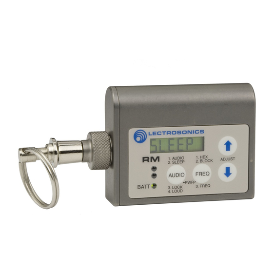
RM
Remote Control
RM2
Remote Control
Fill in for your records:
Serial Number:
Purchase Date:
Technology
®
INSTRUCTION MANUAL
Rio Rancho, NM, USA
www.lectrosonics.com
Advertisement
Table of Contents
Troubleshooting

Related Manuals for Lectrosonics SMQV


Summary of Contents for Lectrosonics SMQV
- Page 1 INSTRUCTION MANUAL SMV Series Super Miniature Variable Power Transmitters With Digital Hybrid Wireless Technology ® US Patent 7,225,135 SMQV Dual battery 50, 100, 250 mW Single battery 50, 100 mW Remote Control Remote Control Fill in for your records: Serial Number:...
-
Page 2: Introduction
The DSP-based design works with all Digital Hybrid receivers, and is backward compatible for use with Lectrosonics 200 Series, 100 Series, IFB receivers and some other brands of analog wireless receivers. LECTROSONICS, INC. -
Page 3: Table Of Contents
Locking or Unlocking the Controls ........10 Attaching and Removing the Microphone ......11 5-Pin Input Jack Wiring ............12 Installing the Connector: .............12 Microphone Cable Termination for Non-Lectrosonics Microphones ..........13 Microphone RF Bypassing ..........14 Line Level Signals ...............14 Wiring Hookups for Different Sources .......15 Compatible Wiring ...............15 Simple Wiring for Servo Bias ..........15... -
Page 4: General Technical Description
SMQV General Technical Description Servo Bias Input No Pre-Emphasis/De-Emphasis The voltage and current requirements of the wide vari- The Digital Hybrid design results in a signal-to-noise ratio ety of electret microphones used in professional appli- high enough to preclude the need for conventional pre-... -
Page 5: Signal Encoding And Pilot Tone
RF intermodulation produced when can also operate in various compatibility modes for use multiple transmitters are used in close proximity to one with Lectrosonics 200 Series, Lectrosonics 100 Series, another (several feet apart). The isolator also provides IFB and certain non-Lectrosonics receivers. Contact... -
Page 6: Controls And Functions
If you wish hexadecimal number that corresponds to the equivalent to use NiMH batteries, we recommend trying Lectrosonics Frequency Switch Setting. fully charged batteries in the unit and using the battery timer feature available in most receivers to The FREQ button is also used with the AUDIO button to determine the available operating time. -
Page 7: Setup Screens
Functions available from the remote control are: the equivalent Lectrosonics Frequency Switch Setting. • Audio Level Repeatedly pressing the •... -
Page 8: Battery Installation
Battery Installation Operating Instructions Power Up and Boot Sequence The SMQV transmitter is powered by two AA batteries. We recommend using lithium batteries for longest life. 1) Ensure that good batteries are installed in the unit. Lithium batteries provide over 7.5 hours of operation at 2)Simultaneously press and hold the AUDIO and room temperature. -
Page 9: Standby Mode
LCD wraps as it reaches the upper or lower end of its range. Note: The unit automatically enters the Standby Mode Most Lectrosonics receivers with an LCD interface with selecting compatibility. indicate the operating frequency both in MHz and as a Power setting two digit hexadecimal number. -
Page 10: Adjusting Audio Level (Gain)
SMQV Adjusting Audio Level (Gain) Locking or Unlocking the Controls The control panel Modulation LEDs indicate the audio The Lock mode protects the level and limiter activity. Once set, the transmitter’s transmitter from accidental audio level setting should not be used to control the changes to its settings. -
Page 11: Attaching And Removing The Microphone
Super-Minature Belt Pack Transmitter Attaching and Removing the Microphone The flexible sleeve over the 5-pin plug on the micro- phone helps prevent dust and moisture from getting into the input jack. A flange is machined into the rim of the connector on the transmitter to help retain the sleeve after it is installed. -
Page 12: 5-Pin Input Jack Wiring
SMQV 5-Pin Input Jack Wiring The wiring diagrams included in this section represent Audio input jack wiring: the basic wiring necessary for the most common types PIN 1 Shield (ground) for positive biased electret lava- of microphones and other audio inputs. Some micro- liere microphones. -
Page 13: Microphone Cable Termination For Non-Lectrosonics Microphones
VHF transmitters with 5-pin shield jacks require a different termination. Lectrosonics lavaliere microphones are terminated for compatibility with VHF and UHF transmitters, which is different than what is shown here. Rio Rancho, NM... -
Page 14: Microphone Rf Bypassing
TA5F Alternate locations for bypass capacitors CONNECTOR Install the capacitors as follows: Use 330 pF capaci- tors. Capacitors are available from Lectrosonics. Please specify the part number for the desired lead style. Leaded capacitors: P/N 15117 Leadless capacitors: P/N SCC330P... -
Page 15: Wiring Hookups For Different Sources
Sanken COS-11. Simplified wiring for microphones such as negative bias TRAM. This wiring is fully compatible with 5-pin inputs on Lectrosonics NOTE: This servo bias wiring is not compatible with earlier transmitters such as the LM and UM Series. This is the wiring versions of Lectrosonics transmitters. -
Page 16: Optional Rm Remote Control
SMQV Optional RM Remote Control The RM unit gives you remote control of SM Series Powering the RM on and off transmitters using an audible tone delivered to the mi- To turn the RM on or off, press the AUDIO and FREQ crophone. -
Page 17: Operating Notes
Loc/unLoc page (via AUDIO) A lower cost alternative to the RM, this model provides Adjust RM volume Loud page (via AUDIO) remote control of: Set SMQV channel (hex) CH page (via FREQ) • Sleep/Unsleep Enable MHz display b (block) page (via FREQ) •... -
Page 18: Troubleshooting
SMQV Troubleshooting Before going through the following chart, be sure that you have a good battery in the transmitter. It is important that you follow these steps in the sequence listed. SYMPTOM POSSIBLE CAUSE TRANSMITTER PWR LED OFF 1) Battery is inserted backwards or dead. -
Page 19: Rm Troubleshooting
Super-Minature Belt Pack Transmitter SYMPTOM POSSIBLE CAUSE HISS AND NOISE -- AUDIBLE DROPOUTS 1) Transmitter gain (audio level) far too low. 2) Receiver antenna missing or obstructed. 3) Transmitter antenna broken or missing. 4) Operating range too great. 5) Signal interference. Turn off transmitter. If receiver’s signal strength indicator does not drop to nearly zero, this indicates an interfering signal may be the problem. -
Page 20: Included Accessories
Connector kit for SMV series Machined, wire belt clip for SMV transmitters, 5-pin TA5F plug with sleeve transmitters, antenna up SMBCDN SMDBC Machined, wire belt clip for SMV Machined, wire belt clip for SMQV transmitters, antenna down and transmitters LECTROSONICS, INC. -
Page 21: Whip Antennas
Super-Minature Belt Pack Transmitter Whip Antennas Lectrosonics AMM Series UHF transmitter antennas follow the color code specifications in the chart below to identify operating frequency block range. (The frequen- cy block range is engraved on the outside housing for each individual transmitter.) If a situation exists whereby... -
Page 22: Specifications And Features
FCC RF exposure guidelines. that may cause undesired operation. Contact Lectrosonics if you have any questions or need more information about RF exposure using this product.. This device complies with FCC radiation exposure limits as set forth for an uncontrolled environment. -
Page 23: Service And Repair
LECTROSONICS’ Service Department is equipped and staffed to quickly repair your equipment. In warranty repairs are made at no charge in accordance with the terms of the warranty. Out-of-warranty repairs are charged at a modest flat rate plus parts and shipping. -
Page 24: Limited One Year Warranty
This warranty does not apply to used or demonstrator equipment. Should any defect develop, Lectrosonics, Inc. will, at our option, repair or replace any defective parts without charge for either parts or labor. If Lectrosonics, Inc. cannot correct the defect in your equipment, it will be replaced at no charge with a similar new item.
Need help?
Do you have a question about the SMQV and is the answer not in the manual?
Questions and answers