
Related Manuals for Sartorius CISL3


Summary of Contents for Sartorius CISL3
- Page 1 Operating Instructions Sartorius Combics 3 Models CISL3 | CIS3 Indicators 98648-011-20...
-
Page 2: Intended Use
Combics is switched on applications, just call or fax your local – Automatic taring when a load is placed Sartorius office. For the address, please on the weighing platform visit our Internet website at: – Optional control through an external www.sartorius.com... -
Page 3: Table Of Contents
Contents Intended Use Service Activating the Service Mode Contents Configuring the Analog/Digital Converter Service Menu Warnings and Safety Precautions Geographical Data Calibration/Adjustment, Linearization, Getting Started Preload Equipment Supplied Installation Instructions Error Codes General View of the Equipment Connecting the Combics to AC Power Care and Maintenance Connecting the External Rechargeable Repairs... -
Page 4: Warnings And Safety Precautions
(with Option L1: IP65); CIS models are carefully before using your Combics. cables, as the pin assignments may rated to IP67. not be compatible with Sartorius Do not use this equipment in hazardous equipment. Check all pin assignments – The IP65/IP67 protection rating areas/locations. -
Page 5: Getting Started
Legal Metrology in the EU* cause harmful interference to radio communications. A sticker with the “Sartorius" logo was affixed to the indicator as a control seal For information on the specific limits following verification. This seal will... -
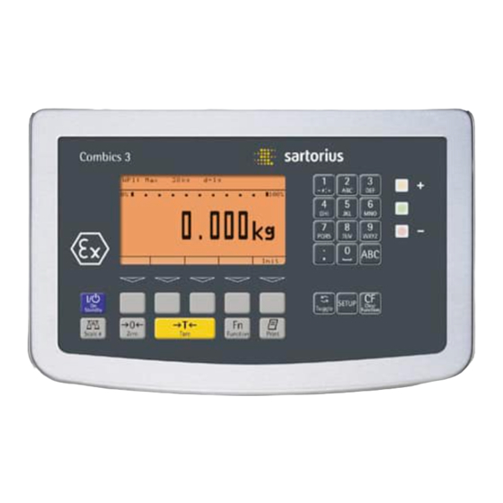
Page 6: General View Of The Equipment
General View of the Equipment Display and Keypad: Combics 3 Display and Keypad LEDs (for checkweighing and classification) Toggle to alphabetical input Alphanumeric keypad CF key (clear function) Settings: Access Setup program Toggle to the application program|application-specific information Data output key Gross/net;... - Page 7 Installing the Weighing Platform The connecting cable should be installed by a trained, certified Sartorius technician. Installation work that affects the IP67 protection rating must be performed with extreme care. Any installation work that does not conform to the instructions in this manual will result in forfeiture of all claims under the manufacturer’s warranty.
-
Page 8: Connecting The Combics To Ac Power
§ Connect the cable to the weighing platform as follows: – Expose approximately 5 cm (2 inches) of the isolated wires for installation. – Remove the casing from approximately 1 cm (1/2 inch) of the wires and attach ferrules to the wire ends. –... -
Page 9: Connecting The External Rechargeable
Connecting a Bar Code Scanner (Accessory; Order No. YBR02CISL) Disconnect the equipment from power. $ Installation: CISL3 models: Connect a 25-pin D-Sub male connector to the COM2 interface. To connect both a bar code scanner and an external rechargeable battery, please use the YTC01T-connector. -
Page 10: Operating Design
Operating Design You can use the Combics 3 to collect weight values from two weighing platforms, calculate and display weight values through application programs, and assign IDs to the samples weighed. Configure the indicator Setup menu for the desired application program first (printer settings, etc.). - Page 11 Soft Keys Text Input Through the Keypad Input Through a Bar Code Scanner or The functions of active soft keys are External Keyboard § Press the a key indicated by symbols and abbreviations Input is analogous to indicator in the last line on the display: keyboard input: >...
-
Page 12: Display
Display Modes Unit and stability: When the weighing system reaches stability, the weight unit or calculation unit Lines for metrological data is displayed here. Bar graph Tare in memory, calculated values: Info/Status line The following symbols may be displayed here: Line for measured values Calculated value (cannot be used in legal metrology) -
Page 13: Data Output
Soft key labels: Error Codes COM Port See the description on page 10. You can define a number of parameters for this SBI interface (print command, ------- – If a key is inactive, “ ” Example: Display in “Setup” mode time-dependent autoprint, ID codes). -
Page 14: Configuration
Configuration You can configure the Combics 3 indi- Setting the Language cator by selecting operating parameters in the Setup menu. The parameters You can choose from five languages are divided into the following groups for the display of information : (highest menu level): –... -
Page 15: Navigating In The Operating Menu
Navigating in the Operating Menu (Examples) Example: Adapting the Combics to “Very unstable conditions” (menu item: “Extreme vibration”) for weighing platform WP1. Switch on the Combics Activate the Setup program Soft key q, Device parameters Select Soft key O and confirm Soft key O, WP-1 Confirm weighing platform... -
Page 16: Defining Password Protection
Defining password protection for the menu: entering, changing or deleting a password Example: Entering, changing or deleting “ABC1” as password Switch on the Combics Activate the Setup program Device parameters 2x soft key q, Select Soft key O and confirm Password Soft key q repeatedly, Select... -
Page 17: Printing The Parameter Settings
-------------------- Printing Parameter Settings 12.01.200 09:46 CIS3 Example: Maximum 20 characters per line. Ser.no 12345678 Vers. 1.0103.11.2 BVers. 01-26-02 -------------------- SETUP DEVICE -------------------- WP-1 Internal COM1 Data communications Baud rate 1200 baud Parity Number of stop b 1 stop bi Handshake mode Hardware 1 charact Number of data b... -
Page 18: Operating Menu Overview (Parameters)
Operating Menu Overview (Parameters) o = Factory setting W = User-defined setting Setup Application Parameters: Please refer to the “Basic Application Programs” manual Fn key o Gross/net toggling Toggle weight units 10 x higher resolution Device Parameters WP-1 RS-232 SBI standard SBI verifiable (trade) o IS-232 ADC-232... - Page 19 Device Parameters WP-1 Internal Stability Delay No delay o Short delay Average delay Long delay Taring Without stability o After stability Auto Zero o On Weight Unit 1 User-defined / o (factory setting: grams Grams / g o Kilograms / kg Carats / ct Pounds / lb Ounces / oz...
- Page 20 Device Parameters WP-1 Internal Weight Unit 2 User-defined / o (factory setting: grams o Grams / g Kilograms /kg Carats / ct Pounds / lb Ounces / oz Troy ounces / ozt Hong Kong taels / tlh Singapore taels / tls Taiwanese taels / tlt Grains / GN Pennyweights / dwt...
- Page 21 Device Parameters COM1 Data Communications o SBI Number of Stop Bits o 1 stop bit 2 stop bits Handshake Mode Software handshake o Hardware, 1 character after CTS Number of Data Bits o 7 bits 8 bits Data Output On request, without stability o On request, after stability Automatic, without stability o 1 display update...
- Page 22 Device Parameters COM1 Data Communications Application Program MP8: 3-3-1 MP8: 3-3-2 MP8: 3-3-3 MP8: 3-3-4 MP8: 3-3-5 MP8: 3-3-6 MP8: 3-3-7 MP8: 3-3-8 MP8: 3-3-9 Program Code 2 o Code 2.1 Code 2.2 Code 2.3 Code 2.4 Baud Rate 150 baud 300 baud 600 baud o 1200 baud...
- Page 23 Device Parameters COM1 Data Communications Handshake Mode Software handshake o Hardware, 1 character after CTS Number of Data Bits o 8 bits Printer 1 YDP01IS o Strip Label Label, manual form feed YDP02 Baud Rate o 1200 baud 2400 baud 4800 baud 9600 baud Parity...
- Page 24 Device Parameters COM1 Printer 1 Universal Baud Rate 150 baud 300 baud 600 baud 1200 baud 4800 baud o 9600 baud 19,200 baud Parity Space Even o None Number of Stop Bits o 1 stop bit 2 stop bits Handshake Mode o Software handshake Hardware, 1 character after CTS o YDP04IS...
- Page 25 Device Parameters UniCOM (Optional Interface) o Off Data Communications: as for COM1, plus: o SBI: as for COM1 xBPI-232: as for COM1 xBPI-485: as for COM2 SMA: as for COM1 Profibus Valid addresses:0 to 126 inclusive; factory setting: 126 Printer 1: ) as for COM1 Printer 2: ) as for COM1...
- Page 26 Device Parameters Printout FlexPrint o Off Printer 1 Number of Printouts o 1 printout 2 printouts Components/Individual Printout o Headers 1, 2 o ID1, ... ID4 o Date and time o Application ini data o Equipment ID (e.g., serial no.) o Application result Printout of Result/Total o Headers 1, 2...
- Page 27 Setup Device Parameters Operating Parameters Display Backlighting o On Auto shutoff acc. to timer Automatic Shutoff Auto off acc. to timer o No automatic shutoff Timer o 1 + 1 minute 2 + 2 minutes 5 + 5 minutes Main Scale o WP-1 WP-2 Display Geographical Data...
-
Page 28: Operation
Operation Soft Key Functions Minimum Load Weighing W To tare container weights automatically, Enter up to four ID codes you need to set a minimum load in the The basic weighing function is always for identifying results on Setup menu, under: accessible and can be used alone or in Application: Weigh: the printout... -
Page 29: Device Parameters
Device Parameters Automatic Shutoff Configure automatic shutoff under Device: Operat.: Acoustic Signal Auto-Off An acoustic signal (single beep) is You can set the timer for this function emitted when you press a key. to two, four or ten minutes, under: A double-beep indicates that the key is Device: Operat.: Timer not currently active. - Page 30 Example: Weighing: Tare the scale by placing a container on the weighing platform Switch on the Combics The automatic self-test runs. Once a readout is shown, the Combics 3 is automatically zeroed and ready to operate. With no load on the platform, you can zero the weighing platform at any time by pressing (.
- Page 31 Example: Weighing: Enter value for tare using the numeric keys; print results Switch on the Combics The automatic self-test runs. Once a readout is shown, the Combics 3 is automatically zeroed and ready to operate. With no load on the platform, you can zero the weighing platform at any time by pressing (.
- Page 32 Toggle to display of net value Print the results -------------------- GMP header (only if GMP-compliant printout is configured) 24.10.2002 10:09 CW3P1-12ED-L Vers. 1.0010.10.2 BVers. 01-26-01 -------------------- End of GMP header EISENSCHMIDT Header lines GOETTINGEN Batch no. 123456 ID codes Cust. Smith 24.10.2002 10:09...
- Page 33 Example: Weighing: Change the tare values, print results, delete tare values Switch on the Combics The automatic self-test runs. Once a readout is shown, the Combics 3 is automatically zeroed and ready to operate. With no load on the platform, you can zero the weighing platform at any time by pressing (.
- Page 34 Read off net weight Print the results 6.433 kg 4.183 kg 0.250 kg 2.000 kg -------------------- Enter a zero (“0”) using the keypad Save the value entered. This deletes tare values; the display shows the gross value. Print the results 6.433 kg 0.000 kg 6.433 kg...
-
Page 35: Data Id Codes
Data ID Codes (Identifiers) You can assign codes (such as product Factory settings for the ID code names: name, batch number, etc.) for identifi- cation of measured values on printouts. ID1: ID2: ID3: Features ID4: – Assign up to four ID codes. –... - Page 36 Example: Entering ID code names. Enter “Batch no.” and “Cust.” as names for ID codes 1 and 2. Activate the Setup program 2 + soft key q Soft key O Select “Device parameters” 6 + soft key q Soft key O Select “Config.
- Page 37 Soft key l Confirm the name for the first ID code Enter the name for ID code 2 (in this example, “Cust.”) Soft key l Confirm the name for the second ID code Delete ID codes “ID3” and “ID4” Soft key l Confirm input Soft key oo Exit the Setup menu...
-
Page 38: Calibration And Adjustment
Operation Calibration and Adjustment Features Preparation § Activate the Setup program: Which of the following features are Purpose Press the M key available depends on the connected § Select “Device Parameters:” weighing platform. These features are Perform calibration to determine the configured in the Setup menu: Press the soft key... - Page 39 Example: External calibration and manual adjustment with default weights (weighing parameters: factory settings) Zero the scale Start calibration (e.g., when adjustment prompt flashes: WP) (press and hold) “Cal” is shown for two seconds You are prompted to place the required weight on the platform (e.g., 10,000 g) Position the calibration weight on the weighing platform...
- Page 40 The difference between the weight value and the true mass is displayed, with +/- sign. External calibration Calibration record is printed, if adjustment was not performed and the process was stopped by pressing ( Nom. 10000 g Diff. + Activate calibration/adjustment (press the ( key to cancel). The calibration weight is displayed at the conclusion of calibration -------------------- A GMP-compliant printout is generated...
-
Page 41: Data Output Functions
Data Output Functions Data is output to the indicator display and to the interfaces. There are two standard interfaces, COM1 and COM2, and an optional multi function interface (UniCOM). Output to the Indicator (Weights and Calculated Values) Lines for metrological data Bar graph Info/Status line Line for measured values... - Page 42 Line for Measured Value/Results This section shows: 5.23r – The current weight value (on verified scales or platforms with e = d, the last digit is bordered for identification as a legal value), or – A calculated value when using an application program, such as Counting or Weighing in Percent Unit This section shows:...
-
Page 43: Interface Port
– YDP01IS – YDP02IS-Label – YDP01IS-Label – Universal Features – YDP02 – YDP04IS – CISL3 indicator (IP44 protection): – YDP03 – YDP04IS-Label Connect via a 25-contact D-Sub – YDP02IS – YAM01IS Alibi memory female connector. If you wish to Network address 0, 1, 2, (...), 31... - Page 44 Data SBI * – Second weighing platform (RS-232 communications xBPI-232 interface) xBPI-485 – External checkweighing display (red/yel- low/green) over the digital I/O (Sartorius Printer 1 YDP01IS Strip * standard) Label – External rechargeable battery pack Printer 2 Label, man. form feed –...
-
Page 45: Generating Sbi Data Output
Combics 3 enables connection of Generating SBI Data Output a second weighing platform, either to the COM1 port or to the UniCOM In the Setup menu, under “Data universal port. Communications: SBI: Data output”, you can define which data is output The standard COM1 port is operated when an output command is received: in the RS-232 mode. -
Page 46: Configuring Printouts
Device Parameters Printing Printout Headers Line 1: Press the p key to output data to the Line 2: printer port. If the Setup program is active, the menu ID codes ID1: settings are printed. ID2: – The printout is generated once the SBI ID3: command “Esc k P _”... - Page 47 Information Blocks Date/Time Enabling GMP-compliant Printouts When this block is enabled, the printout Select “ISO/GLP/GMP printout” to add The individual information blocks are appears as follows (example): a GMP header and a footer bracketing shown below with detailed explana- the measured result on the printout. If tions.
-
Page 48: Sample Printouts
Sample Printouts Neutral Measurement Application – Result = Weight: The “Initialization data” block contains the The deviation from the nominal weight reference sample quantity and reference is given both as a percentage and as an For details on the individual information weight. - Page 49 Classification Application Net-total Formulation Application Individual printout when a component is saved in tare memory by pressing O The “Initialization data” block contains The “Initialization data” block is empty. the upper limits of Classes 1 through 4. Which data is contained in the “Results” The “Results”...
- Page 50 Printout of components GMP-compliant Printout ‘Set preload’ record: Example with 3 transactions: The GMP-compliant printout consists of -------------------- 3 sections (see also the section entitled 14.01.2002 13:50 HEADER LINE 1 “Enabling GMP-compliant Printouts,” CIS3 HEADER LINE 2 above): Ser.no. 12345678 14.07.2002 09:43 –...
-
Page 51: Data Output Format
Data Output Format (Line Format) You can output the value displayed in the measured value line Error Codes and the weight unit, with or without a data ID code. Whether the data ID code is included in the output depends on your Pos. -
Page 52: External Keyboard Functions (Pc Keyboard)
Error Codes Automatic Data Output (SBI) You can have results of measurement printed automatically Pos. 1 2 3 4 5 6 7 8 9 10 11 1213 14 15 16 17 18 19 20 21 22 You can configure the autoprint function to print at certain S t a t * * * * * E r r * * # # * * * * CRLF intervals (measured in display updates )) and define whether... -
Page 53: Data Input Format
You can connect a computer to your Command Meaning Handshake indicator to send commands controlling The scale interface (Sartorius Balance Trigger T key function (tare) scale functions and applications via the Interface = SBI) has transmit and receive Trigger n key function kNW_ interface port. -
Page 54: Pin Assignment Chart
Pin Assignment Charts Model CISL3 (IP44 Protection) Model CIS3: COM1 and COM2 female connectors: Terminals on the PCB COM1: 11-20 1-10 UniCOM: 1-4 Battery: 1-4 COM2: 1-10 25-contact D-Submini female connector (DB25S) with screw lock hardware Front view Male interface connector used... - Page 55 Connections in the CIS3 Diagram (on the left): top view Terminal assignments in the 10-contact COM2 terminal strip: RS-232 RS-422 RS-485 No. 1: Not connected Not connected Not connected No. 2: No. 3: No. 4: +5 V switch +5 V switch +5 V switch No.
- Page 56 Setting the Interface Operating Mode for COM2 Coding for COM2 in Model CISL3 RS-232 RS-422 RS-485 Solder bridge J2: open closed closed Solder bridge J9: open open closed Solder bridge J10: open open closed Coding for COM2 in Model CIS3...
- Page 57 Connecting Cables to Interfaces Cables should be connected by a certified technician who has received specialized training from Sartorius. § Make sure to use the connecting cable with screw-lock hardware (see “Accessories”). Make sure to disconnect the equipment from power before connecting cables.
-
Page 58: Cabling Diagram
IP67-protection. For details, contact the Sartorius Service Center. Cabling Diagram (Adapter Cable for PC) (CISL3 indicator: Adapter cable 7357312; CIS3 indicator: Adapter cable YCC02-D9F6). Diagram for connecting a computer or other peripheral device to the indicator using the RS-232C/V24 standard and cables up to 15 m (50 ft.) long: Cabling Diagrams Connection assignments for the cable from the indicator to an RS-232 PC interface. - Page 59 Cabling Diagram (Adapter Cable for PC) Indicator 25 pin 9 pin — — Cable type: AWG 24 specification...
-
Page 60: Service
Service Activating the Service Mode Purpose When the Service mode is active, an “S” The Service mode allows access to an is shown on the right-hand side of the extended menu. This mode must be header line in the Setup menu. activated before you can perform calibration To deactivate the Service mode, restart the and adjustment work on the Combics and... -
Page 61: Configuring The Analog/Digital Converter
For example, any commercially available strain-gauge The following advanced functions are in the “Calibration/Adjustment” menu, load cell or analog Sartorius CAPP, available: the “External calibration” item is not CAPS, IU or IF weighing platform by displayed if the connected weighing... - Page 62 When you return to the highest level of Descriptions of the Individual Menu Multiple range mode – the Setup menu by pressing the o soft key Items A multiple-range scale has two or three repeatedly, you are prompted to save the Standard/Verifiable: Select and load weighing ranges.
-
Page 63: Geographical Data
Range 1, Range 2, Range 3 Save Parameters Geographical Data Here you can enter the limits for each Select “Yes” by pressing the Q soft key of the weighing ranges. When a limit and press l to confirm; the A/D con- This is a submenu of the “Calibration/ is exceeded, the accuracy changes. - Page 64 Overview of the Setup Menu in Service Mode o = Factory setting x = User-defined setting Input of the Setup Application parameters service password Fn key function Device parameters (“Device parameters” menu structure depicted below) Info Language Factory settings: all parameters Setup Device (Device parameters)
- Page 65 Setup Device see previous page (Device parameters) Enter the service COM-1 o Off password for access o RS-232 SBI standard SBI verifiable o IS-232 (see menu “WP1 - RS-232 - IS-232”). ADC-232 (see menu “WP - Internal” Data communications Printer 1 (see “Operating Menu Overview (Parameters)”...
- Page 66 Setup Menu for A/D Converter Configuration Access Setup in Service mode WP1 - Internal - WP1 - ADC configuration Standard Ranges Single range mode Scale interval d configuration Max. cap. Multi-interval mode Scale interval d Range 1 Range 2 Range 3 Max.
- Page 67 A/D Converter Configuration (Examples) Example 1: Configuring the A/D Converter with a Weighing Platform Connected Preparation (see also “Calibration and Adjustment” in the chapter entitled “Operating the Combics”) § Remove the cap that covers the menu access switch on the left-hand side of the back of the indicator §...
- Page 68 If necessary: soft key , soft key Ranges Select the menu item. Single range mode In the example shown here, has been selected (marked by o). To select a different weighing range configuration, proceed as follows: Press the q soft key to move the highlight bar downward (or, if necessary, press the Q soft key to move it upward) and open this submenu by pressing the O key (see below).
- Page 69 The illustration on the left shows an example of the input menu opened when Multi-interval scale when the range configuration defines a Multiple range scale The same is shown for a This example shows the parameters for a scale in “Verifiable” configuration, with 2 weighing ranges and a maximum capacity of 6.000 kg: –...
- Page 70 Restart the weighing instrument: Turn the indicator off and then on again. The Sartorius logo is displayed briefly, after which the device is in normal weighing mode. The displays depicted in the next two illustrations on the left show data from a multi-interval configured as described above, or a similarly configured multiple-range scale.
- Page 71 Example 2: A/D Converter Configuration with Load Cell(s) Connected: Calibration/Adjustment without Weights Preparation (see also “Calibration and Adjustment” in the chapter entitled “Operating the Combics”) § Remove the cap that covers the menu access switch on the left-hand side of the back of the indicator §...
- Page 72 “WP1 - Internal” level of the “Device Parameters” menu. Restart the weighing instrument: Turn the indicator off and then on again. The Sartorius logo is displayed briefly, after which the device is in normal weighing mode. Device parameters...
- Page 73 Setup menu for the “WP1 - Internal” level of the “Device Parameters” menu (for details, see the first segments of Examples 1 and 2). Soft key q, soft key O Calibration/adjustment Open the menu. 5+ soft key q Adjust without weights Select the menu.
- Page 74 § Replace the protective cap over the menu access switch. Restart the weighing instrument: Turn the indicator off and then on again. The Sartorius logo is displayed briefly, after which the device is in normal weighing mode.
- Page 75 The following data, describing the place of the “Geographical Data” menu, To display geographical data during of manufacture (Sartorius in Goettingen, which is a submenu of the “Calibra- the adjustment procedure, select Weender Landstrasse 94-108) is used as tion/Adjustment”...
- Page 76 When the display of geographical data is latitude (in degrees). Again, press ) to confirm the data or active, the calibration procedure is as fol- ( to cancel the adjustment routine. lows: When the calibration procedure is started The calibration weight is now prompted. Altitud ), the display shows If the gravitational acceleration is given...
- Page 77 The illustration on the left shows an example in which the currently valid parameters for the weighing platform have been entered under “Latitude” and “Altitude.” After this data was saved and the scale returned to weighing mode, this pair of values is displayed again the next time the input menu is opened. The input field for gravitational acceleration is empty (display shows “0.000000”).
- Page 78 Return to the normal weighing mode. Restart the weighing instrument: Turn the indicator off and then on again. The Sartorius logo is displayed briefly, after which the device is in normal weighing mode. Calibration and Adjustment (for more details, see “Calibration and Adjustment” in the chapter entitled “Operation”) Settings: §...
- Page 79 Altitud The display shows for 2 seconds. Extern. cal. factory-def. w The elevation at the place of installation is displayed in meters above sea level. In the example shown here, the elevation setting for “Germany (Zone D)” is displayed. Confirm the displayed value or press ( to cancel the calibration procedure. Latitud The display shows for 2 seconds.
- Page 80 Restart the weighing instrument: Turn the indicator off and then on again. The Sartorius logo is displayed briefly, after which the device is in normal weighing mode. If the A/D converter was configured with a “Verifiable” data record, the lines for display of metrological data (lines 1 and 2) show the data valid for use in legal metrology, if the menu access switch is closed.
-
Page 81: Preload
Calibration/Adjustment, Linearization, Setting and Clearing the Preload Entering Calibration and Linearization Weights Preparation (See also “Calibration and Adjustment” in the chapter entitled “Operation.”) § Remove the cap that covers the menu access switch on the left-hand side of the back of the indicator housing. - Page 82 Changing linearization weight 1: 1 . 5 0 0 Enter the new value (in this example, 1.5 kg) and press the l to confirm. The highlight bar is automatically positioned on the field for the next linearization weight (“Lin. wt.2”). Soft key l Enter or change up to four linearization weights in sequence as needed.
-
Page 83: Calibration/Adjustment, Linearization
(external calibration/adjustment with a user-defined weight) and “Cal key blocked” are also accessible without activating the Service mode. Restart the scale: Turn the indicator off and then on again. The Sartorius logo is displayed briefly, after which the device is in normal weighing mode. - Page 84 If nec.: Unload and zero the scale. (> 2 sec) Start external calibration/adjustment. This display is shown for 2 seconds. Important Note: If the display of geographical data (elevation and latitude or gravitational acceleration) is activated (see “Settings” at the beginning of this section), this data is displayed; press ) to confirm each value (to cancel the calibration/adjustment procedure, press ().
- Page 85 § Unload the scale. Restart the scale: Turn the indicator off and then on again. The Sartorius logo is displayed briefly, after which the device is in normal weighing mode. Note: If a serious operator error should occur during calibration (for example, if the menu setting “Cal.
- Page 86 § Unload the scale. Restart the scale: Turn the indicator off and then on again. The Sartorius logo is displayed briefly, after which the device is in normal weighing mode. Note: If a serious operator error should occur during calibration, refer to the “Note” above for details on corrective measures.
- Page 87 Restart the scale: Turn the indicator off and then on again. The Sartorius logo is displayed briefly, after which the device is in normal weighing mode. Unload and zero the scale.
- Page 88 After approx. 2 seconds, the target value for linearization weight 1 is shown as a negative value on the display (in example shown here, 1.500 kg) . § Place the prompted weight on the scale. After a brief pause, the difference since the most recent calibration is displayed. $ Press ( if you wish to cancel linearization at this point.
- Page 89 Adjust the scale; to do this, store linearization weight 3. After linearization weight 3 has been stored, the target value for linearization weight 4 is shown as a negative value on the display (in this example: 6.000 kg). § Place the prompted weight on the scale. After a brief pause, the difference since the most recent calibration is displayed.
-
Page 90: Preload
The “Set Preload” item is marked by a circle (o). Restart the scale: Turn the indicator off and then on again. The Sartorius logo is displayed briefly, after which the device is in normal weighing mode. Unload and then tare or zero the scale. -
Page 91: Preload
Display after the scale has been zeroed. § Place the preload weight on the weighing platform. (> 2 sec) Activate the “Set preload” function. This display is shown for 2 seconds. The weight on the scale is stored as the preload. SET VOR Set preload After the “Set Preload”... -
Page 92: Preload
Restart the scale: Turn the indicator off and then on again. The Sartorius logo is displayed briefly, after which the device is in normal weighing mode. § Remove the preload from the weighing platform. The display shows the preload weight as a negative value. - Page 93 § Replace the protective cap over the menu access switch. Restart the scale: Turn the indicator off and then on again. The Sartorius logo is displayed briefly, after which the device is in normal weighing mode. If the A/D converter was configured with a “Verifiable” data record, the lines for display of metrological data (lines 1 and 2) show the data valid for use in legal metrology when the menu access switch is closed.
- Page 94 Connecting a Weighing Platform to WP 2 displayed after you close the menu access COM1 (Recommended) or COM2 Port): switch (see also the notes on this topic at the beginning and end of this chapter, When you connect a digital weighing plat- as well as the “Calibration and Adjustment”...
- Page 95 Entering the Service Date Preparation (See also “Operating Menu (Overview)” in the chapter entitled “Configuration” and refer to the service manual for Combics Complete Scales and Indicators.) § Activate the Service mode and open the Device parameters menu (see the corresponding section at the beginning of this chapter). Soft key q repeatedly Service Select the...
- Page 96 Soft key q repeatedly Memory number Select the menu item. Soft key O Memory number Open the menu item. Navigation and Input For details, see Example 1 under “Configuring the Analog/Digital Converter” and refer to the chapter entitled “Operating Design.” Enter the new start value for the transaction number and press the l soft key to confirm.
-
Page 97: Error Codes
Cause Solution ERR 101 Key is stuck Release key or Key pressed at power on Contact your local Sartorius Service Center ERR 320 Program memory defective Contact your local Sartorius Service Center ERR 335 Verified weighing platform not compatible Connect a compatible weighing platform... -
Page 98: Care And Maintenance
$ Lock it in a secure place to ensure that outlet (mains supply) and disconnect any data cables. it cannot be used for the time being, $ Notify your nearest Sartorius Service Make sure no liquid enters the indicator housing. Center or the International Technical... -
Page 99: Overview
Display Housing: – Material AISI 304 stainless steel – Dust and water protection acc. to EN60529 CISL3: IP44 (optional IP65) CIS3: IP67 Operating temperature range –10°C to +40°C (+14°F to +104°F) Power supply 100-240 VAC (-15/+10%), 50-60Hz, max. 17W / 23 VA optional 15.5-24 VDC (±10%), max. -
Page 100: Dimensions (Scale Drawings)
Dimensions (Scale Drawings) All dimensions are given in millimeters... -
Page 101: Accessories
Verifiable strip and label printer with thermal print head, YDP12IS-0CE-UV paper width 101 mm, with adapter cable (12-contact round male connector) and external power supply. Sartorius “NICE Label Express” software required for putting the printer into operation. Adapter cable YCC01-01CISLM3 required for Combics model CISL indicator. - Page 102 SartoConnect data transfer software for connecting your YSC01I Sartorius scale to a computer running Windows 95/98/NT. Load weighing data in an application such as MS Excel or Access. Includes a cable (1.5 m) for connecting the scale to a PC...
- Page 103 Product Order No. Retainer for a bar code scanner, for attachment to floor-mounted column, bench stand or complete scale retainer YBH01CWS Plate for attaching a printer to the floor-mounted YPP01CWS column or bench stand Castor set (2 guide castors, 2 lockable castors) for YBP03CIP/S floor-column base YRO03CI Anti-theft locking device...
-
Page 104: Declarations Of Conformity
The operator shall be responsible for any modifications to Sartorius equipment and for any connections of cables or equipment not supplied by Sartorius and must check and, if necessary, correct these modifi- cations and connections. On request, Sartorius will provide information on... -
Page 110: General Password
Appendix: General Password Activate the Setup program 2+ soft key q, Device parameters Select (or Application parameters) soft key O and confirm You are prompted to enter the password Enter numbers Enter the General Password (see below) Soft key l Confirm the password The parameter menu is displayed Soft key q (repeatedly, if necessary) - Page 111 – Software: MS Excel® version 8 declaration of compatibility. of Sartorius AG. All rights defined under (included with MS Office 97) or later copyright law are reserved by – VGA graphics adapter, 800x600 pixels, Start Sartorius AG.
- Page 112 Sartorius AG Weender Landstrasse 94–108 37075 Goettingen, Germany Phone +49.551.308.0 +49.551.308.3289 www.sartorius.com Copyright by Sartorius AG, Goettingen, Germany. All rights reserved. No part of this publication may be reprinted or translated in any form or by any means without the prior written permission of Sartorius AG.
Need help?
Do you have a question about the CISL3 and is the answer not in the manual?
Questions and answers