
Related Manuals for Sartorius Combics 3 Series


Summary of Contents for Sartorius Combics 3 Series
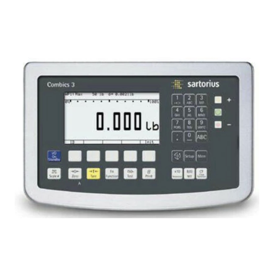
- Page 1 Operating Instructions Sartorius Combics 3 Models CAISL3 | CAIS3 Indicators 98648-018-29...
-
Page 2: Table Of Contents
External Linearization with Factory-Defined Weights Sartorius Services ....... . . 114 (Default Weights) . -
Page 3: Notes On Using This Manual
Read the safety precautions carefully. This manual is part of the product. Keep it in a safe and easily accessible location. If the manual should be lost or misplaced, please contact Sartorius for a replacement or download the latest manual from our website: www.sartorius.com... -
Page 4: Warning And Safety Instructions
Weighing Instruments" and the to immunity) is available on request. Declaration of Conformity. – A sticker with the “Sartorius" logo was If you have any problems with your affixed to the indicator as a control device, contact your local Sartorius seal following verification. -
Page 5: Device Description
Device Description Description Combics 3: – Is robust and durable, thanks to its stainless steel housing. – Is easy to clean and disinfect. – Is easy to operate, thanks to the following features: – Large, backlit, fully graphical dot-matrix display –... -
Page 6: General View Of The Equipment
General View of the Equipment Display and keypad Display and Keypad Alphanumeric keypad LEDs (for checkweighing and classifica- tion) Toggle key for alphabetic input Configuration: Access to the product data memory Delete key Configuration: Access to Setup Toggles the display between gross value (net value plus tare) and net value (gross value minus tare) Toggles between application... -
Page 7: Getting Started
Installation When an indicator is ordered with special equipment, the desired options come pre-installed from the factory. Storage and Shipping Conditions Unpacked devices can lose their precision if subject to extreme vibrations. Excessive vibrations may compromise the safety of the equipment. –... -
Page 8: Connecting A Weighing Platform To Wp 1
“Data Interfaces." Connecting Weighing Platforms to WP1 An analog Sartorius platform (CAPP, CAPS, IU or IF) or a commercially-available DMS load cell can be connected to the Combics indicator WP1 input. The load cell should be connected by a certified technician who has received specialized training from Sartorius. -
Page 9: Connecting A Weighing Platform To Wp 2
After you close the housing again, use a pressure gauge to check the integrity of the IP69K protection. For details, contact the Sartorius Service Center. Connecting Cables Insert all cable wires through the ferrite case, wind them around the ferrite case and then reinsert back through the ferrite case. -
Page 10: Interface Pin Assignments Com1, Com2 And Ps2 With Options
Getting Started Interface Pin Assignments COM1, COM2 and PS2 with Options Digital PCB CAIS3 (IP69K) COM1, COM2 and PS2 terminal assignments (applies to all PCBs) PS2 COM1 COM2 1 LOAD_PRINTER 11 Clear to Send (CTS) 21 5 V switched Weighing platform 2 RESET_OUT 12 Data Terminal Ready (DTR) 22 PS2_Daten... -
Page 11: Interface Pin Assignment Chart Com1
Getting Started Interface PCB for RS-232/RS-485 for IS platforms (option A62/A72) PS2 COM1 COM2 A62/72 A62/A72 terminal assignments 11 TxD/RxD+ Weighing platform Interface 1 12 TxD/RxD- 13 LINE_OUT 14 LINE_OUT 15 GND Calibration Lock 16 GND Keypad LED + Display LED + Display Keys Interface Pin Assignment Chart COM1... -
Page 12: Connecting A Pc Via Interface Com1
Getting Started Connecting a PC via Interface COM1 Use the following cables to connect a PC to the indicator in accordance with the RS-232C/V24 standard (max. cable length 15 m): Model type CAISL: connecting cable 7357312 Model type CAIS: connecting cable YCC02-D9F6 RS232 Pin Assignment Pin assignments for the cable from the indicator to an RS-232 PC interface (COM1). -
Page 13: Interface Pin Assignment Chart Com2
Getting Started Interface Pin Assignment Chart COM2 Model type CAISL (IP-44 protection) COM2 female connectors: 9-pin D-Submini female connector (DB9S) with screw lock hardware for cable gland Recommended interface connector: 9-pin D-Submini (DB9) with shielded cable clamp assembly and shield plate and fastening screws (Amp type 164868-1) Pin assignment: Pin 1... -
Page 14: Connecting A Pc Via Interface Com2
Getting Started Connecting a PC via Interface COM2 Use the following cables to connect a PC to the indicator in accordance with the RS-232C/V24 standard (max. cable length 15 m): Model type CAISL: connecting cable 7357312 Model type CAIS: connecting cable YCC02-D9F6 RS232 Pin Assignment Pin assignments for the cable from the indicator to an RS-232 PC interface (COM2). -
Page 15: Interface Pin Assignment Chart Ps2
Getting Started Interface Pin Assignment Chart PS2 Model type CAISL (IP-44 protection) PS2 female connector: 6-pin miniature socket PS2 (Mini-DIN) Recommended interface connector: 6-pin miniature socket PS2 with integrated shielded cable clamp assembly Pin Assignments: Keyboard data (data interface cable) Not assigned Internal ground (GND) +5 V switched... -
Page 16: Closing The Combics Indicator
Make sure that the voltage rating printed on the manufacturer's ID label is identical to that of your local line voltage. If the voltage specified on the label or the plug design of the AC adapter do not match the rating or standard you use, please contact your Sartorius office or dealer. -
Page 17: Configuring Weighing Platforms
Configuring Weighing Platforms Service Mode Purpose The Service mode enables access to additional menu items in the Setup menu which are not displayed when the Service mode is not active. The most important calibration and adjustment work for the indicator and for the connected weighing platform can be carried out in the Service menu, e.g. -
Page 18: Overview Of The Setup Menu In Service Mode
Geographical latitude Altitude Gravitational acceleration Save parameters o No ) Equipment version: – then blocked internally ) = Not available on devices verified for use in legal metrology ) only when operated with Sartorius IS weighing platforms or an external ADC... - Page 19 Configuring Weighing Platforms Device Parameters Internal Calibration/Adjustment unit Grams /g Kilograms /kg Tons /t o Pounds /lb Menu items “Adapt filter" - “Factory settings: only bal. func," see the “Setup Overview (Parameters)" section COM-1 (when the WP is assigned to this interface) COM-2 (when the WP is assigned to this interface) UNICOM (only if available) WP2, see the “Setup Overview (Parameters)"...
-
Page 20: Setup Menu For Adc Configuration
Configuring Weighing Platforms Setup Menu for A/D Converter Configuration Setup access in Service mode WP1 - Internal - ADC configuration Standard configuration Ranges Single-range mode Scale interval d Max. cap. Multi-interval mode Scale interval d Range 1 Range 2 Range 3 Max. -
Page 21: Analog/Digital Converter
Configuring Weighing Platforms Analog/Digital Converter (ADC) Purpose Adjust the parameters of the analog/digital converter to the connected load cell or weighing platform. After ADC configuration, the ADC in connection with the load sensor is defined as a scale. Once the ADC configuration has been locked, the indicator can no longer be used to influence weighing results. - Page 22 Configuring Weighing Platforms Scale interval d Scale interval d indicates the resolution of the weighing instrument. The scale interval d can be entered only in increments of 1, 2, 5, 10, 20, etc. When using verifiable or verified weighing platforms, the scale interval d is the same as the verification scale interval e.
-
Page 23: Analog/Digital Converter (Adc) Configuration
Configuring Weighing Platforms Analog/Digital Converter (ADC) Configuration The weighing platform must already be connected. Open the menu access switch The menu access switch is located on the back of the indicator right next to the weighing platform connection. Remove the cap. Slide the switch to the left (= “open"... - Page 24 Configuring Weighing Platforms The default values displayed depend on the data record loaded and might have to be changed. In the example shown here, the A/D configuration is set with a “Verifiable” data record in single-range mode. Single-range mode Select the individual input fields using the “ "...
- Page 25 Configuring Weighing Platforms Multi-interval mode The illustration shows an example of the input menu opened for multi-interval mode range configuration. This example shows the parameters for a scale in “Verifiable” configuration, with 2 weighing ranges and a maximum capacity of 6.000 kg. –...
- Page 26 Configuring Weighing Platforms To save the configuration, use the “ " soft key to select “ " and confirm using the “l" soft key. The message “ Function activated " appears briefly. The program then returns automatically to the regular weighing mode. To not save the configuration: Press the “...
-
Page 27: Entering Geographical Data For Use In Legal Metrology
Configuring Weighing Platforms Entering Geographical Data for Use in Legal Metrology Purpose Entering geographical data allows the external adjustment of weighing equipment at a place (e.g. at the manufacturer or vendor's place of business) that is not the same as the place of installation. - Page 28 Configuring Weighing Platforms Procedure Remove the cap. Slide the menu access switch to the left (= “open" position). If the device is part of a verified weighing facility, this will only be possible if the verification seal is broken. The weighing equipment must then be verified again. Activate the Service mode, see “Service Mode."...
- Page 29 Configuring Weighing Platforms Entering Gravity Use the “ " or “ " soft key to select the corresponding input field. Enter gravity in m/s via the keypad and confirm using the “l" soft key. Permissible value range: 9.700000 9.900000 d < gravity 2 d < In the example shown here, the value for gravity has been changed.
- Page 30 Configuring Weighing Platforms Press J to start an external adjustment. C.EXT.D The display “ " appears briefly. In the example, the altitude and latitude of the installation location are being entered. C.EXT.D C.EXT.DEF. Altitud The display “ " appears briefly. Altitud C.EXT.DEF.
- Page 31 Configuring Weighing Platforms Gravity If gravity is being entered instead of altitude and latitude, then “ " is displayed for a brief time after “ ." The entered value appears in m/s , here for the “Germany (Zone D)" setting. Press J to confirm the displayed value or press ( to cancel the adjustment.
-
Page 32: Entering Adjustment And Linearization Weights
Configuring Weighing Platforms Entering Adjustment and Linearization Weights Purpose Entering adjustment and linearization weights. Procedure See also “Calibration and Adjustment" in the chapter called “Operation". Remove the cap. Slide the menu access switch to the left (= “open" position). Activate the Service mode, see “Service Mode." Select weighing platform “... - Page 33 Configuring Weighing Platforms Function Allocation of the allocation for the J Key for Calibration/Adjustment Purpose The J key is used for the calibration/adjustment function. Key settings can be changed when the Service mode is activated: Procedure Remove the cap. Slide the menu access switch to the left (= “open" position). Activate the Service mode, see “Service Mode."...
-
Page 34: External Calibration/Adjustment With Factory-Defined Weight (Default Weight)
" can also be accessed without activating the Service mode. Press e to turn off the device. Press e turn the device back on. The Sartorius logo is displayed briefly, after which the device is in normal weighing mode. Press ( to unload and zero the scale. - Page 35 Press e to turn off the device. BVers. 01-63-02 Press e turn the device back on. -------------------- External calibration The Sartorius logo is displayed briefly, after which the device is in normal weighing mode. Nom. 5.000 kg Diff. + 0.010 kg External adjustment Diff.
-
Page 36: External Calibration/Adjustment With A User-Defined Weight
" input field. Press e to turn off the device. Press e turn the device back on. The Sartorius logo is displayed briefly, after which the device is in normal weighing mode. Press ( to unload and zero the scale. -
Page 37: Internal Calibration/Adjustment
Press e to turn off the device. BVers. 01-63-02 Press e turn the device back on. -------------------- External calibration The Sartorius logo is displayed briefly, after which the device is in normal weighing mode. Nom. 6.000 kg Diff. + 0.010 kg External adjustment Diff. -
Page 38: Adjustment Without Weights
Configuring Weighing Platforms Adjustment Without Weights Purpose In the Service menu, adjustment without weights can be carried out by entering the characteristic data of the load cells. Adjustment without weights may not be carried out on weighing equipment used in legal metrology. - Page 39 Configuring Weighing Platforms The Input menu is displayed. Enter the nominal capacity and resolution of the load cells in kg and the sensitivity of the load cells in mV/V in the corresponding input fields. The maximum capacity is usually less than the value to be entered in the “...
-
Page 40: Function Allocation Of The J Key For Linearization And Setting/Deleting The Preload
Configuring Weighing Platforms Function Allocation of the J Key for Linearization and Setting/Deleting the Preload Purpose The J key is normally used for the calibration/adjustment function. The following additional functions can be allocated to the key when the Service mode is activated: –... -
Page 41: External Linearization With Factory-Defined Weights (Default Weights)
Configuring Weighing Platforms External Linearization with the Factory-Defined Weight (Default Weights) Setup information – This function is accessible only if the software and the functionality of the connected weighing platform permit this operation. – External linearization when weighing in legal metrology is only possible when the menu access switch is open. -
Page 42: External Linearization With User-Defined Weights
Configuring Weighing Platforms External Linearization with User-Defined Weights Setup information – This function is accessible only if the software and the functionality of the connected weighing platform permit this operation. – External linearization when weighing in legal metrology is only possible when the menu access switch is open. - Page 43 Configuring Weighing Platforms Press J to apply linearization weight 1 or press ( to cancel the linearization function. After the linearization weight 1 has been saved you will be prompted to place the second linearization weight on the weighing pan. Repeat the procedure for all required linearization weights.
-
Page 44: Setting The Preload
For scales used in legal metrology, slide the menu access switch to the left (= “open" position). Press e turn the device back on. The Sartorius logo is displayed briefly, after which the device is in normal weighing mode. Press ( to unload and zero the scale. Display after the scale has been zeroed. -
Page 45: Deleting The Preload
(= “open" position). Press e turn the device back on. The Sartorius logo is displayed briefly, after which the device is in normal weighing mode. Remove the preload weight from the weighing platform. The display shows the removed preload weight as a negative value. -
Page 46: Operating Design
Operating Design You can use the Combics 3 to record weight values from 1 to 3 weighing platforms, calculate and display weight values through application programs, and assign IDs to the samples weighed. Configure the indicator first, using the Setup menu for the desired application program (printer settings, etc.). - Page 47 Operating Design Soft keys The functions of active soft keys are indicated by symbols and abbreviations in the last line on the display. Abbreviation examples: : ID list : Delete entry DELETE Symbols used for soft key functions: : Return to initial state Next higher menu level Show items under selected entry Scroll up in the input/output window...
-
Page 48: Saving Settings In Weighing Mode
Operating Design Special Character Input via the Keypad Press the a key. “ABC" is displayed. Press the 1 key. The corresponding character selection is displayed. The flashing cursor marks the first character. Press the F1 soft key ( ) or wait 2 seconds. The special character appears on the display. -
Page 49: Display In Weighing Mode
Operating Design Display in Weighing Mode Weighing Mode: Display of Measured and Calculated Values The display is divided into several sections. Lines for metrological data Bar graph Info/Status line Lines for metrological data The following parameters are shown here: Line for measured values Maximum capacity (upper weighing range limit) of the active weighing platform Text lines... -
Page 50: Leds
Operating Design Application, printing and battery symbols Printing in progress GMP-compliant printout active Battery status: ‘Battery fully charged’ or ‘Battery empty’ Bar graph The bar graph shows the percentage of the weighing platform’s capacity that is “used up” by the load on the scale (gross value). Lower load limit 100% Upper load limit... -
Page 51: Menu Operating Design
Operating Design Menu Operating Design Operating example: Setup:Device parameters: WP 1:Internal:Adapt filter Marks the current menu setting Configuring parameters: Soft key “Q" or “q": Parameter settings Soft key “l": Confirm parameter M or “ ": Exit Setup menu Menu display Display Mode for Configuration and Information (Setup) The display is divided into three sections. -
Page 52: Configuration
Operating Design Configuration You can configure the indicator by selecting parameters in the Setup menu. These are divided into the following groups (menu level 1), menu structure see section the “Setup Overview (Parameters)" section – Application parameters – Fn key function –... - Page 53 Operating Design Setting up Password Protection Press e to turn on the device. Press M. The menu appears on the display. Press the “ " soft key several times to select the “ Device parameters " line. Press the “ "...
- Page 54 Operating Design Setting up Password Protection Press e to turn on the device. Press M. The menu appears on the display. Press the “ " soft key several times to select the “ Device parameters " line. Press the “ "...
- Page 55 Operating Design Printing Parameter Settings Example: Maximum 20 characters per line. -------------------- 12.01.2010 09:46 Type CAIS3 Ser.no 12345678 Vers. 1.02.101110 BVers. 01-63-02 -------------------- SETUP DEVICE -------------------- WP 1 Internal WP 2 off COM1 Data communcations Baud rate 1200 Baud Parity Number of Stop bits 1 Stop bit Handshake mode...
-
Page 56: Setup Overview (Parameters)
1 digit o 2 digits 4 digits 8 digits ) Equipment version: – then blocked internally ) Not available on devices verified for use in legal metrology ) Only when operated with Sartorius IS weighing platforms or an external ADC... - Page 57 Operating Design Device Parameters WP 1 Internal Stability delay Without delay o Short delay Average delay Long delay Taring Without stability o After stability Autozero o On Weight unit 1 User-definable / o (factory setting: grams) Grams /g o Kilograms / kg Carats / ct Pounds / lb Ounces / oz v)
- Page 58 Operating Design Device Parameters WP 1 Internal Weight unit 2 User-definable / o (factory setting: grams) o Grams / g Kilograms / kg Carats / ct Pounds / lb Ounces / oz Troy ounces / ozt Hong Kong taels / tlh Singapore taels / tls Taiwan taels / tlt Grains / GN 1)
- Page 59 Operating Design Device Parameters WP 1 Internal Weight unit 3 User-definable / o (factory setting: grams) o Grams / g Kilograms / kg Carats / ct Pounds / lb Ounces / oz Troy ounces / ozt Hong Kong taels / tlh Singapore taels / tls Taiwan taels / tlt Grains / GN 1)
- Page 60 Operating Design Device Parameters COM 1 o Off WP 3 o RS-232 SBI standard (9600 baud) SBI verifiable (9600 baud) o IS-232 ADC-232 Data communications o SBI Baud rate 150 baud 300 baud 600 baud o 1200 baud 2400 baud 4800 baud 9600 baud 19200 baud...
- Page 61 Operating Design Device Parameters COM 1 Data communications o SBI Line format For raw data (16 characters) o For other apps. (22 characters) Sign format Do not output + sign o Output + sign Factory setting o No XBPI RS-232 Baud rate 150 baud 300 baud...
- Page 62 Operating Design Device Parameters COM 1 Printer 1 YDP20 Baud rate o 1200 baud 2400 baud 4800 baud 9600 baud 19200 baud Parity Space o Odd Even Number of stop bits o 1 stop bit 2 stop bits Handshake mode Software handshake o Hardware 1-char YDP14IS...
- Page 63 Operating Design Device Parameters COM 2 similar to COM 1 UNICOM (optional interface) o Off WP 3 o RS-232 SBI standard (9600 baud) SBI verifiable (9600 baud) o IS-232 ADC-232 RS-485 o IS-485 ADC-485 Data communications o SBI similar to COM 1 xBPI-232 similar to COM 1 xBPI-485 address 0 to 31 can be selected SMA similar to COM 1...
- Page 64 Operating Design Device Parameters I/O control Input ports Universal switch key p Print key p Print key - long ) Tare key o J ISO-Test key k Fn key n WP toggle key Comb. tare/zero function (zero if possible, otherwise tare.) ( Zero key e On key c CF key...
- Page 65 Operating Design Device Parameters Config. printout Printer 1 Number of printouts o 1 printout 2 printouts Indiv.: Printout f. app./weighing List <-> Selection Gross (G#) Space line Tare -------- Net (N) Form feed Space line Date/time Time GMP header GLP footer Transaction no.
- Page 66 Operating Design Device Parameters Operating parameters Acoustic signal o On Linked to the green LED Keypad Block key functions All keys unblocked All blocked except e Alphanumeric keys blocked Weighing platform switch disabled Zero key blocked Tare key blocked Fn key blocked ISO-Test key blocked Print key blocked 10X higher resolution key blocked...
- Page 67 Operating Design Device Parameters Clock Time: Date: Test I/O ports Set internal outputs Int. output 1 (Lighter) Int. output 2 (Equal) Int. output 3 (Heavier) 0 Int. output 4 (Set) Read internal inputs Int. input 1: Passwords Password: SQmin Display o No GMP print o No...
- Page 68 Operating Design Setup Info Service Service date: Terminal Model: Serial no. Basic ID: Version no.: (application software version) 1. WP 1 Model Version no.: (software version) Serial no. Latitude: Altitude: Grav. acc.: Access switch 2. WP 2, see WP 1 3.
-
Page 69: Operation
Operation Weighing This application is always available during operation. Features – Zeroing by pressing ( – Storing the weight on the platform as a tare by pressing ) – Tare container weight automatically – Use a barcode scanner to enter tare weight –... - Page 70 Operation Minimum load for automatic taring and automatic printing To tare container weights automatically, you need to set a minimum load in the Setup menu, under: “ Application parameters:Min. load f. auto. taring/printout:o 10 digits " You can set the following for the minimum load: 1 digit (no minimum load) 2 digits 5 digits...
- Page 71 Operation Using a barcode scanner to enter an identifier Identifiers can be entered via a barcode scanner. Operating menu setting: “ Device parameters:Bar code:oID " The value is applied and saved automatically. Scanning barcodes directly You can directly scan a barcode using the barcode scanner. Operating menu setting: “...
-
Page 72: Adjustment/Configuration Counter For Standard Scales
Operation Adjustment/Configuration counter for standard scales Purpose Automatic recording of changes to adjustment and weighing parameters using two independent counters. The values remain saved for the life of the component. To display both counters, press and hold the ( key for longer than 2 seconds. The “Configuration counter"... -
Page 73: Device Parameters
Operation Device Parameters Password protection Access to device and application parameters can be password-protected against unauthorized changes in the Setup menu under “ Device parameters: Password ," see the “Setting up Password Protection" section in the “Operating Design" chapter. Acoustic Signal An acoustic signal (single beep for active, double beep for inactive keys) is emitted when you press a key. - Page 74 Operation Tare the scale by placing a container on the weighing platform Press the e key to turn on the indicator. The automatic self-test runs. When the weight readout is shown, the scale is ready to operate and automatically set to zero.
- Page 75 Operation Weighing with numeric entry of tare value and printing the results. Press the e key to turn on the indicator. The automatic self-test runs. When the weight readout is shown, the scale is ready to operate and automatically set to zero.
- Page 76 Operation Press the L key to toggle back to the previous display. Press the p key to print the results. -------------------- Start of GMP header (only if GMP-compliant printout is configured). 24.10.2010 10:09 Type CAW3P1-12ED-L Vers.no. 1.02.101110 BVers. 01-63-02 -------------------- End of GMP header EISENSCHMIDT Headers...
- Page 77 Operation Weighing with variable tare values, printing results, deleting tare values Press the e key to turn on the indicator. The automatic self-test runs. When the weight readout is shown, the scale is ready to operate and automatically set to zero.
- Page 78 Operation Read the Net weight. Press the p key to print the results. 6.433 kg 4.183 kg 0.250 kg 2.000 kg -------------------- Press the 0 key. Press the ) key to apply the entered value. The tare values are deleted. The gross value appears on the display. Press the p key to print the results.
-
Page 79: Calibration And Adjustment
Operation Calibration and Adjustment Purpose Perform calibration to determine the difference between the value displayed and the actual weight on the platform. Calibration does not entail making any changes within the weighing equipment. During adjustment, the difference between the measured value displayed and the true weight of a sample is corrected, or is reduced to an allowable level within maximum permissible error limits. - Page 80 Calibrate first; then adjust automatically or manually (not for verified weighing instruments) under “… Calibration/adjustment:Cal/adj. sequence " For Sartorius IS weighing platforms only: Flashing WP symbol as adjustment prompt (If more than one weighing platform is connected, the platform number is also displayed) under Calibration/adjustment:CAL key function “…...
-
Page 81: External Calibration And Manual Adjustment With Default Weights (Weighing Parameters: Factory Settings)
Ext. cal./adj.; factory-def. wt. Ext. cal./adj.; user-defined wt. Key blocked Cal./adj. sequence Cal. then auto adj. o Cal. then manual adj. isoCAL function (for Sartorius IS weighing platforms only) o Off Adjustment prompt Activate ext. adj. o Activated Deactivated... - Page 82 Operation Place the calibration/adjustment weight on the weighing platform. The difference between the measured value and the true weight of the sample will be displayed with plus/minus signs. External calibration A printout will be generated if the adjustment is not carried out and the procedure is Nom.
-
Page 83: Sqmin Function
Operation SQmin Function Purpose To display the allowable minimum sample quantity “SQmin” (sample quantity minimum) in accordance with the United States Pharmacopoeia (USP). According to USP guidelines, the uncertainty of measurement may not exceed 0.1% of the sample quantity when substances are weighed with the highest degree of accuracy for volume determination. -
Page 84: Sqmin Operation
Operation SQmin Operation Configuration in Service Mode The SQmin value can only be entered in Service mode. Remove the cap. Slide the menu access switch to the left (= “open" position). If the device is part of a verified weighing facility, this will only be possible if the verification seal is broken. - Page 85 Operation Procedure Place the container for the sample on the scale and press the ) key to tare. Place the sample on the scale. The minimum sample quantity is not reached (symbol Press the p key to generate the printout. Place another sample on the scale.
-
Page 86: Data Id Codes
Operation Data ID Codes You can assign codes (such as product name, batch number, etc.) for identification of measured values in all application programs. Features – Assign up to six ID codes. – Assign both a name and a value to each ID code. –... -
Page 87: Using Individual Id Codes
Operation Using Individual ID Code Example Enter ID code names. “Batch no." and “Customer" should be entered for ID 1 and ID 2. Press the M key and select “ Device parameters:Config. printout:ID codes ." The first line is selected. Press the a key to enter “Batch no."... -
Page 88: Data Interfaces
The free cable ends are connected via the screw terminals. Warning when using third-party RS-232 connecting cables: The pin assignments may not be compatible with Sartorius equipment. Check the pin assignment against the cabling diagrams and disconnect any lines that are not assigned. -
Page 89: Specifications
Data Interfaces Specifications Interface operating mode: Full duplex Serial interface: Level: COM1: RS-232, COM2: RS-232, UniCOM (optional): RS-232 or RS-422/485 half duplex Connection: IP44 devices: 25-pin D-Sub socket IP69K devices: Connection via screw terminals in the housing, cable routed into the housing via a cable gland. Transmission rate: 150, 300, 600, 1200, 2400, 4800, 9600, 19200 baud (depending on the operating mode) -
Page 90: Connection Options
PC (RS-232 interface) – Third weighing platform (RS-232 interface) – External checkweighing display (stop light) via a digital I/O (Sartorius standard), COM1 only – To PS2: Barcode scanner/External keyboard The following devices can be connected to the optional UniCOM universal interface: –... -
Page 91: Configuring The Data Interface As A Com Port
Data Interfaces Configuring the Data Interface as a COM Port For operation as a COM port, you can adapt data records to the following operating modes: – SBI (factory setting) – XBPI-232 – XBPI-485 – In the SBI communication mode, you can control a display unit and a connected weighing platform by sending ESC commands from a PC to the communications port (COM1, COM2 or UniCOM). -
Page 92: Setting The Sbi Data Output
Data Interfaces Setting the SBI Data Output Data output settings can be made in the Setup menu under “ Data communications:SBI:Data output ." The following options are available: – The displayed value, with or without stability check – Automatic output of the displayed value, either with or without stability check, or automatically at defined intervals –... - Page 93 Data Interfaces Example The command character for output is “P" (“output to Port"). To trigger this command, send the string: “ESC P CR LF”. Command Meaning Weighing mode 1 Weighing mode 2 Weighing mode 3 Weighing mode 4 Block keys Send display value to data interface Output acoustic signal Unblock keys...
-
Page 94: Data Output Format
Data Interfaces Data Output Format You can output the value displayed in the measured value line and the weight unit, with or without a data ID code. Whether the data ID code is included in the output depends on your settings under “Line Format." Examples 235 pcs without ID code... - Page 95 Data Interfaces Output of the weight value +1255.7 g Position 12 13 Position 1: Plus +, or minus - or space Position 2: Space Positions 3-10: Weight value with decimal point; leading zeros are output as spaces. Position 11: Space Positions 12-14: Characters for unit of measure, space or ! sign as a symbol Position 15:...
- Page 96 Data Interfaces Gross value Stat Status Classx Classification, class x Net value Application tare memory 1 Limx Class limit Application tare memory 2 Percentage (as loss) Diff Difference from calibration value Percentage (as residue) Targ. Exact adjustment weight value Wxx% Reference percentage weight Nom.
-
Page 97: External Keyboard Functions (Pc Keyboard)
Data Interfaces External Keyboard Functions (PC Keyboard) For settings, go to the Setup menu under “ Device parameters: Bar code:External keyboard ." The alphanumeric key codes implemented here are specific to the German keyboard layout. The following alphanumeric characters are used (some require the “Shift” key): a - z, A - Z, 0 - 9, <space>, and these characters: ,.\+’<>/»$@%/();=:_?* Function keys: PC keyboard... -
Page 98: Configuring The Data Interface As A Printer Port
Data Interfaces Configuring the Data Interface as a Printer Port Device Parameters Config. printout Headers Line 1: Line 2: Identifiers ID1: ID2: ID3: ID4: ISO/GMP o Off Protocol For several application results Date/ o Date with time Time Date only Once at Stability o Off... -
Page 99: Printout Configuration
Data Interfaces There are several actions that generate the command for outputting data to the printer port: Pressing the p key. – If the operating menu is active, all menu settings under the active menu level are printed. – In some applications, pressing a given key (e. g., to save a value or start a routine) also generates a print command, or it is generated automatically depending on the application configuration. -
Page 100: Gmp-Compliant Printouts
Data Interfaces Application Initialization Data Which data is included in this block depends on the active application. In the “Counting" application, for example, the reference sample quantity and reference weight are printed (plus a blank line). "Counting" print block example: nRef 10 pcs wRef... -
Page 101: Sample Printouts
Data Interfaces “Neutral Measurement” application – Weight display: Sample Printouts In the OK and nonconforming range, The initialization data block contains For details on the individual the deviation from the target weight the reference sample quantity and information blocks, see “Configuring is always printed as a percentage and reference weight. - Page 102 Data Interfaces “Classification” Application “Net-total Formulation” Application Printout of third component generated by pressing p. The initialization block contains the The Initialization data block is empty. upper limits of weight classes 1, 2, 3, 4. The data that is contained in the results block depends on the program The results block contains gross, 4.400 kg...
- Page 103 Component printout, GMP-compliant printouts Setting the preload printout example with 3 transactions: -------------------- The GMP-compliant printout consists of 3 sections (see also the section 14.01.2010 13:50 entitled “Enabling GMP-compliant Type CAIS3 HEADER LINE1 Printouts,” above): Ser.no. 12345678 HEADER LINE2 Vers. 1.02.101110 14.07.2010 09:43...
-
Page 104: Error Codes
Display Cause Solution ERR 101 - 104 Key is stuck Release key or contact Sartorius customer service Key pressed when switching on device ERR 320 Operating program memory faulty Contact your local Sartorius Service Center Verified weighing platform not compatible... -
Page 105: Care And Maintenance
Care and Maintenance Service Regular servicing by a Sartorius technician will extend the service life of your equipment and ensure its continued weighing accuracy. Sartorius offers its customers service contracts with regular maintenance intervals ranging from one month to two years. The frequency of the maintenance intervals depends on the operating conditions and the operator's tolerance requirements. -
Page 106: Cleaning Stainless Steel Surfaces
Disconnect the power supply to the device (unplug the power cord from the mains supply) and make sure the device cannot be used for the time being. Notify your nearest Sartorius Service Center. Maintenance and repair work may only be carried out by service technicians: –... -
Page 107: Disposal
In Germany and many other countries, Sartorius AG takes care of the return and legally compliant disposal of its electrical and electronic equipment. These products may not be placed with household waste or brought to collection centers run by local public disposal operation - not even by small commercial operators. -
Page 108: Specifications
Specifications ADC scale interface 2*3000e (option A8) When used in standard applications (as opposed to legal metrology): – Display resolution <31250 d 625 d – Lowest permissible input signal Using the Equipment in Legal Metrology: l, m Accuracy class Verification scale intervals when used as: –... -
Page 109: Adc Scale Interface 10,000E (Option A10)
Specifications ADC scale interface 10,000e (Option A20) When used in standard applications (as opposed to legal metrology): – Display resolution <100.000 d 1510 d – Lowest permissible input signal Using the Equipment in Legal Metrology: l, m Accuracy class Verification scale intervals when used as: –... -
Page 110: Device Dimensions
Device Dimensions M4 (3x) All data in mm... -
Page 111: Accessories
Accessories Product Order No. Verifiable printer with functions for date, time and statistical evaluations and LC display. YDP20-0CE – 5+ 50 m paper rolls for data printer 6906937 – Replacement ink ribbon cartridge for printer 6906918 Verifiable strip and label printer with barcode printout, paper width 108 mm, with adapter cable (12-pin round male connector) and external power supply. - Page 112 (50 mA) and 7 TTL-compatible inputs (0 - 30 V), YCC02-RELAIS01/02 connection cable required YSB02 Relay box to connect Combics 2 to external control units, YCC02-RELAIS01/02 connection cable required VF3033 Software Sartorius Nice Label Express (SNLE) YAD02IS WinScale for Windows YSW03 SartoCollect YSC02 Other functions...
- Page 113 - for printer YDP12/04IS, 9-pin D-SUB plug, 6 m YCC02-D09M6 - for printer YDP20-0CE or PC, 9-pin D-SUB socket, 6 m YCC02-D09F6 - for Sartorius scales, 25-pin D-SUB plug, 6 m YCC02-D25M6 - for various accessories, 25-pin D-SUB socket, 6 m YCC02-D25F6...
-
Page 114: Documents And Services
For information on verification and legal regulations currently applicable in your country, and to obtain the names of the persons to contact, please contact your local Sartorius office, dealer, or Service Center. Further information concerning verification can be obtained from our customer service... -
Page 115: Declaration Of Conformities
Declarations of Conformity CE Directive 2004/108/EC and CE Directive 2006/95/EC... - Page 116 Declarations of Conformity CE Directive 2002/95/EC...
- Page 117 Declarations of Conformity...
-
Page 118: Ec Type-Approval Certificate
Declarations of Conformity... -
Page 119: Test Certificate
Test Certificate... -
Page 120: Plates And Markings
Plates and Markings... - Page 121 Plates and Markings...
- Page 122 Plates and Markings...
- Page 123 Plates and Markings...
-
Page 124: Appendix: Guide To Verification Of Weighing Instruments
The documents required to verify a weighing instrument for legal metrology can be created using the data, documents, and programs available from the Sartorius website. The printout of the completed forms is valid as a model for verification of the weighing instrument produced by the scale manufacturer. - Page 125 Copyright: This documentation may not be duplicated or transmitted for any purpose whatsoever, either in whole or in part, without the express written permission of Sartorius AG. All rights defined under copyright law are reserved by Sartorius AG. The program is intended for use by the purchaser only. Transfer to third parties, whether free of charge or in return for payment, is not permitted.
-
Page 127: Appendix: General Password
Appendix: Passwords Service Password Press e to turn on the device. y When turned on the scale is in an application program. Enter the service password and confirm with the M key. y The device in now is Service mode. An “ "... - Page 130 Sartorius AG. All rights reserved by Sartorius AG in accordance with copyright law. The information and figures contained in these instructions correspond to the version date specified below.
Need help?
Do you have a question about the Combics 3 Series and is the answer not in the manual?
Questions and answers