
Related Manuals for Sartorius Midrics 1


Summary of Contents for Sartorius Midrics 1
- Page 1 Operating Instructions ® ® Sartorius Midrics 1| Midrics Models MIS1 | MIS2 Indicators 98648-014-89...
-
Page 2: Intended Use
Intended Use ® The following symbols are used in The Midrics 1 and 2 indicators are these instructions: robust indicators for demanding, daily § Indicates required steps quality control. They meet the highest $ Indicates steps required only under requirements placed on the accuracy certain conditions and reliability of weighing results in the >... -
Page 3: Table Of Contents
Contents 2 Intended Use 49 Operation 49 Weighing W 4 Warning and Safety Information 49 Device Parameters 50 Tare Function in Weighing 5 General View of the Device 51 Numeric Input for Weighing 5 Display and Keypad 52 Weighing with Variable Tare Values 5 Rear View 53 Calibration, Adjustment 55 Data ID Codes (Identifiers) -
Page 4: Warning And Safety Information
B) it has according to the Declaration of thoroughly before the device is used. – Use only Sartorius accessories and Conformity included. Be sure to observe options as these are perfectly tailored the information of this Declaration. -
Page 5: General View Of The Device
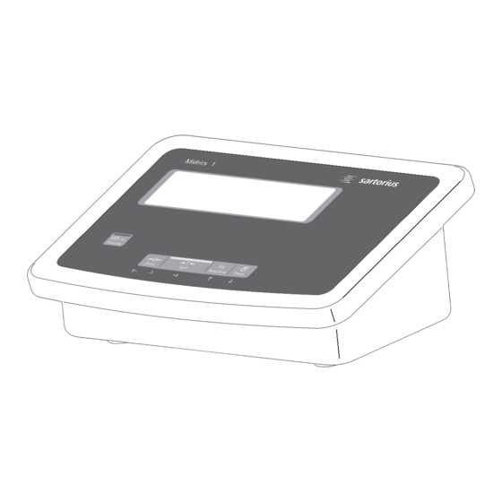
General View of the Device ® Display and Keypad Midrics 1 Display (For a detailed diagram, please see the chapter “Operating design”) 2 ON/Standby key 3 Zeroing key 4 Tare key 5 Function key (e.g. switch gross/net) 6 Print key (data output) 7 Clear key (function application- dependent) 8 Reference value key (function... -
Page 6: Start-Up
Start-up Unpacking Start up the device § Unpack the device and check it immedi- $ If necessary, acclimatize the device: ately for any visible damage. see next column $ If you detect any damage, proceed as § Connect the weighing platform and the directed in the chapter entitled “Care indicator, see page 7 (any type of and Maintenance“, under “Safety... -
Page 7: Connecting The Weighing Platform
The load cell should be connected by a certified technician who has received specialized training from Sartorius. Any installation work that does not conform to the instructions in this manual results in forfeiture of all claims under the manufacturer’s warranty. - Page 8 The printed voltage rating (see type label) must match the voltage in the place of instal- lation. If the stated supply voltage or the plug design of the power cord does not comply with the standard you use, please inform your nearest Sartorius representative or your dealer.
-
Page 9: Analog/Digital Converter (Adc)
Description of the Individual Menu Scale Interval d Analog/Digital Converter Items for the A/C Converter The scale interval d indicates the reso- (ADC) Configuration lution of the weighing instrument. The scale interval can only be entered Purpose Standard or verifiable configuration in increments of 1, 2, 5, 10, 20, etc. -
Page 10: Menu Structure For Adc Configuration
Range 1, Range 2, Range 3 Available weighing units (menu item Testing and configuration (RANGE 1, RANGE 2, RANGE 3) UNITS) for operation in legal metrology The range limits are entered for the This menu item is used to select the A metrology plate is included in the individual ranges. - Page 11 UNITS Available weight units FREE User-defined unit Gram Kilogram Carat Pound Ounce Troy ounce Hong Kong taels Singapore taels Taiwan taels Grain Pennyweights Milligram Parts per pound Chinese taels Mommes Austrian carat Tola Baht Mesgahl LB/OZ Pounds per ounce SAVE VERIF.
-
Page 12: Service Menu
The following additional functions are Service Menu available in the service mode: Purpose The following are the menu items The service menu enables access to displayed behind the menu items date additional menu items in the setup (“DATE”) and code (“CODE”): menu, which are not displayed when –... -
Page 13: Activating The Service Mode
Activating the Service Mode Switch the device on and immediately (during the initialization of the device) press ..briefly to display the menu Select the Setup menu item setup Confirm the setup menu item wp-1 Select the code menu item (press key k until the code appears on the display) code Confirm the code menu item and enter the service password (see Appendix) -
Page 14: Configuring The A/D Converter
Configuring the A/D Converter Open the menu access switch § Remove the cap that covers the menu access switch on the left-hand side of the back of the indicator § To do this, move the switch to the left (towards the interface connectors). (“open position”) Activate the service mode (see page 13) Select weighing platform and confirm: Press the ) key... - Page 15 Example 1: Example 2: Enter or change values for standard configuration in single range Enter or change values for standard configuration in a multi- mode in the unit set under 1.7.x. interval scale in the unit set under 1.7.x. (the same applies for multiple range mode). ADC-CON Select menu item ADC CON ADC-CON...
- Page 16 Example 3: Example 4: Enter or change values for verifiable configuration in single range Enter or change values for verifiable configuration in a multi-inter- mode in the unit set under 1.7.x. val scale in the unit set under 1.7.x. (the same applies for multiple range mode). ADC-CON Select menu item ADC CON ADC-CON...
-
Page 17: Key ) - > 2 Sec Function Allocation
Key ) - > 2 sec Function – External linearization with the lineariza- Once linearization has been completed, tion weights (menu item 1.9.7) entered or after a preload has been set or Allocation under menu item 1.18 cleared the function of the key )- > 2 –... -
Page 18: Enter Geographical Data
Set-up Information Note: Entering Geographical The set geographical values are displayed – It is only possible to enter geographical Data data when the menu access switch is during the calibration procedure if the open. display of the data has been activated Purpose –... -
Page 19: Enter Calibration And Linearization
– Calibration and linearization weights Procedure Enter Calibration are entered in the Setup menu under – Activate the service mode (only neces- and Linearization Weights “WP 1”. The settings are made in the sary if linearization weights are going corresponding Setup menu under menu to be entered) Purpose item 1.18. -
Page 20: External Linearization
After external linearization, close the External Linearization menu access switch and reallocate the original function back to the key ) Set-up information –> 2 sec (e.g. external calibration/ External linearization when weighing in adjustment with user-defined weights) legal metrology is only possible when under menu item 1.9. -
Page 21: Calibration, Adjustment
Features – Display of elevation and geographical Calibration, Adjustment latitude, or gravitational acceleration The configured weighing platform determines which of the following after CAL has been displayed at the Purpose features are available: start of the calibration procedure (menu The accuracy of the measurement item 8.12.2). - Page 22 Position the calibration/adjustment weight on the weighing platform The difference between the measured value and the true weight of the sample will be disayed with plus/minus signs. External calibration A printout will be generated if the calibration is not carried out and the procedure 10000 g can be stopped by pressing the ( key.
-
Page 23: Set Preload
Set Preload Clear Preload Set-up Information Set-up Information It is only possible to set a preload when It is only possible to clear a preload the menu access switch is open. when the menu access switch is open. – The function set preload (menu item –... -
Page 24: Enter Serial Number Of The Weighing Platform
Enter Serial Number of the Weighing Platform Click on the menu item Setup setup Select Setup device parameters wp-1 Click on the menu item Code (press key k until the code appears in the display) code Select the menu item Code, enter the service password (see Appendix) and save, then return to menu item Code (see also page 13). -
Page 25: Operating Design
Operating Design Keys ® ® Operation of the Midrics 1 or Midrics 2 scale involves just a few keys. These keys have one function during measurement and another during configuration. Some of the keys have one function when pressed briefly and another activated by pressing and holding the key for longer than 2 seconds. -
Page 26: Input Through The Digital I/O Port
Numeric Input Through the Keypad (Midrics 2 only) § To enter numbers (one digit at a time): Press 0, 1, 2 …9 § To save input: press the required key (e.g., ) to save manual tare input) § To delete a digit: Press c Loading a Tare Value from the Weighing Platform... - Page 27 Operating Design Display in Weighing Mode 9. Numeric display; e.g., showing Verified models only: reference value (Midrics 2 only) 14. The “zero-setting" symbol is displayed The illustration above shows all display segments and the symbols and other after the active scale or weighing elements used during normal weighing Midrics 2: platform has been zeroed...
-
Page 28: Calculated Values
Bar graph Saving Data in Weighing Mode The bar graph shows the percentage of the All of the application parameters weighing platform's capacity that is “used saved (e.g., reference values) remain in up" by the load on the scale (gross value). memory and are still available after –... -
Page 29: Data Output
You can connect two strip or label no characters entered yet: Delete Select and save a menu item printers to the Midrics 1 or Midrics 2 entire string and enter a space – Press and hold (> 2 seconds): and have printouts generated at the –... -
Page 30: Configuration
Configuration You can configure the Midrics scale Setting the Language by selecting parameters in the operating menu. The parameters are combined Example: Selecting “U.S. Mode" for the language in the following groups (this is the highest menu level): Switch on the scale –... -
Page 31: Entering Or Changing The Password
Entering or Changing the Password Example: Assign a password (in this example, ) to protect the application program settings APPL and the device parameters SETUP from unauthorized changes 1. Switch on the scale 9. Enter the second character using the p and k keys (in this example: 2. -
Page 32: Operating Menu Overview
Configuration Operating Menu Overview You can configure the Midrics to meet Menu levels are identified by texts, and numeric codes identify the individual settings. individual requirements by entering user data and setting selected parameters = Setting/function available on Midrics 2 only in the operating menu. - Page 33 Operating Menu = Setting/function available on Midrics 2 only * Factory setting Menu Application Programs appl Basic weighing function 3.5. Minimum load for automatic taring and automatic printing 3.5.1* 1 digit 3.5.2 2 digits 3.5.3 5 digits 3.5.4 10 digits 3.5.5 20 digits 3.5.6...
- Page 34 Configuration appl Z nm Neutral Measurement 3.5. Minimum load for automatic taring and automatic printing Numeric menu as for Weighing 3.6. Minimum load for initialization Numeric menu as for Counting 3.7. Automatic taring: first weight tared 3.7.1* 3.7.2 3.8. Start application and load most recent application data when the Midrics is switched on 3.8.1 Automatic (on) 3.8.2*...
- Page 35 appl Averaging (Animal Weighing) 3.21. Static display of result after load removed 3.21.1* Display is static until unload threshold reached Display is static until c is pressed 3.21.2 3.25. Tare function 3.25.1* Add input value (weight value) for taring 3.25.2 Tare value can be overwritten 9.1.
- Page 36 Configuration appl Classification 3.8. Start application and load most recent application data when the Midrics is switched on 3.8.1 Automatic (on) 3.8.2* Manual (off) 3.25. Tare function 3.25.1* Add input value (weight value) for taring 3.25.2 Tare value can be overwritten 4.3.
- Page 37 appl Net-total Formulation (2 Tare Memory) 3.5. Minimum load for automatic taring and automatic printing Numeric menu as for Weighing 3.6. Minimum load for automatically saving/transferring values Numeric menu as for Counting 3.7. Automatic taring: first weight tared 3.7.1* 3.7.2 3.17.
-
Page 38: Parameters
Configuration Device Parameters Setup Password prompt displayed if a password is configured wp-1 Weighing platform 1 (Display designation of this menu level: 1) 1.1. Adapt weighing instrument to ambient conditions (adapt filter) 1.1.1 Very stable conditions 1.1.2* Stable conditions 1.1.3 Unstable conditions 1.1.4 Very unstable conditions... - Page 39 Setup wp-1 Calibration and adjustment 1.9. 1.9.1* External calibration/adjustment; default weight 1.9.3 External calibration/adjustment; weight can be selected under menu item 1.18.1 1.9.8. Set preload 1.9.9. Clear preload No function when you press and hold ) > 2 sec 1.9.10 Calibration/adjustment sequence 1.10.
- Page 40 Setup Com1 Interface port 1 (optional) (Display designation of this menu level: 2) datProt Data protocol SBI: standard version 5.1. Baud rate 5.1.1 150 baud 5.1.2 300 baud 5.1.3 600 baud 5.1.4* 1200 baud 5.1.5 2400 baud 5.1.6 4800 baud 5.1.7 9600 baud 5.1.8...
- Page 41 Setup Com1 datProt SMA interface function 5.1. Baud rate 5.1.1 150 baud 5.1.2 300 baud 5.1.3 600 baud 5.1.4 1200 baud 5.1.5 2400 baud 5.1.6 4800 baud 5.1.7* 9600 baud 5.1.8 19,200 baud 5.2. through 5.6. Numeric menu as for SBI Printer Printer configuration DP01IS...
- Page 42 Setup Com1 Printer Uni-pri Universal interface 5.1. Baud rate 5.1.1 150 baud 5.1.2 300 baud 5.1.3 600 baud 5.1.4 1200 baud 5.1.5 2400 baud 5.1.6 4800 baud 5.1.7* 9600 baud 5.1.8 19,200 baud 5.2. Parity 5.2.2 Space 5.2.3 5.2.4 Even 5.2.5* None Number of stop bits...
- Page 43 Setup unicom Interface port 2 (Optional) (Display designation of this menu level: 3) datprot Data protocol SBI: standard version 5.1. through 9.1. Numeric menu as for COM1 bpi-232 XBPI-232 bpi-485 XBPI-485 0 to 31 Network address: From 0 to 31 inclusive SMA interface function 5.1.
- Page 44 Setup uniCom1 Second interface (optional) Printer Printer configuration YDP01IS YDP01IS line Strip printer label Label printer lab ff Label printer with manual feed YDP02 YDP02 5.1. through 5.4. Numeric menu as for COM1 YDP03 YDP03-0CE 5.1. through 5.4. Numeric menu as for COM1 YDP02IS YDP02IS line...
- Page 45 Setup ctrl io Control inputs/outputs (Display designation of this menu level: 5) ctr inp Control inputs For YDO01M-232CO; Option A1 8.4. Function for external control inputs (TTL) Trigger p key function 8.4.1* Trigger p key (> 2 sec) function 8.4.2 Trigger ) key function 8.4.3 Trigger ) key (>...
- Page 46 Configuration Setup prtprot Printouts (Display designation of this menu level: 7) 7.4. Header input 7.4.1 (blank) Header line 1 (max. 20 characters); example: “MEYER'S" 7.4.2 (blank) Header line 2 (max. 20 characters); example: “STEEL" 7.4.3 (ID 1) ID code name for ID 1 (max. 40 characters) 7.4.4 (ID 2) ID code name for ID 2 (max.
- Page 47 Setup prtprot 7.10. Optional “UniCOM” interface Print results when c pressed in Totalizing and Net-total applications 7.10.1* Header lines 1, 2 (input: see code 7.4.x) 7.10.2* Date and time 7.10.4* Weighing instrument designation 7.10.5* Result from the application program 7.10.6* ID codes 1 to 4 7.10.7 2 additional blank lines...
-
Page 48: Parameters
Setup time Time (optional) Format for setting the time (example): 10.07.41 (hours.minutes.seconds) date Date (optional) Format for setting the date (example): 01.05.07 (day.month.year); U.S. mode: (month.day.year) code Password Set, change and delete password here. Max. 8 characters); example: 12345678 Device information Info Service Service information... -
Page 49: Operation
Operation Automatic Taring Basic Weighing Function Device Parameters The first weight on the scale that exceeds the preset minimum load is Weighing W Keys stored in the tare memory at stability. The basic weighing function is always The keypad can be blocked. The values for subsequent loads are accessible and can be used alone or in There are four settings to choose from:... - Page 50 Example with Midrics 2: Switch on; zero; tare container weight; place sample in container; toggle display to gross weight, second weight unit or 10-fold higher resolution; print results. Display with tared scale and 1. Switch on the scale sample in container All display segments are shown for about 1 second (self-test)
- Page 51 Example with Midrics 2 Example with Midrics 2: Tare the scale by placing a container on the weighing platform Enter the tare value using the keypad; print the results 1. Switch on the scale 1. Switch on the scale The automatic self-test runs. The automatic self-test runs.
- Page 52 Example with Midrics 2: Weigh with varying tare values; print the results; delete tare values Read the net weight 1. Switch on the scale The automatic self-test runs. Once a readout is shown, the Midrics is automatically zeroed and ready to operate. Press ( to reset the 7.
-
Page 53: Calibration/Adjustment
– Specify the weight for external Preparation Calibration and Adjustment calibration/adjustment: § Switch on the scale: Press e Setup Purpose § While all segments are lit, wp-1 Perform calibration to determine the dif- press the ) key 1.18. : (Enter calibration weight) ference between the value displayed and §... - Page 54 Example: External calibration and manual adjustment with default weights (weighing parameters: factory settings) 1. Zero the scale. The difference between measured value and the true mass is shown with a plus 2. Start calibration or minus sign. (e.g., after calibration prompt: flashing symbol).
-
Page 55: Data Id Codes (Identifiers)
Example with Midrics 2: Data ID Codes Enter ID code names. Enter “Batch no." and “Cust." as names for ID codes 1 and 2. Midrics 2 only: You can assign codes (such as product name, batch number, etc.) for identifi- 1. - Page 56 4. Place sample on the platform 9. Enter the first character using 5. Print the weight value the p and k keys (in this example, the first character is “ ") ID code 2 24.02.2006 10:09 ------------------- Ser.no 12345678 1083 g 10.
-
Page 57: Averaging
Application Programs Applications: Overview Midrics 1 Midrics 2 Keypad 5 keys 11 keys + numeric keypad Display 14-segment 14-segment plus application symbols Applications Basic weighing Averaging (animal weighing) Print/send data record to peripheral device Label printing Counting Totalizing Checkweighing Batching to a target value... - Page 58 Application: Counting Z With the Counting program you can – Restore factory settings. Configuration: determine the number of parts that Appl 9.1. each have approximately equal weight. Before the quantity on the platform Features can be calculated, the reference sample –...
- Page 59 Preparation Minimum Load Parameter for Saving Weight Values To tare container weights automati- The weight on the platform is saved § Switch on the scale: Press e cally, set the minimum load in the as a reference when the platform has §...
- Page 60 Example: Determining the number of uncounted parts. Settings (changes in the factory settings required for this example): Setup: Application: Counting Setup: PRTPROT (printout): 7.7.x (COM1) (see “Configuration” for options) Set the minimum load to a lower number of digits or increase the reference sample quantity and the number of parts in the container.
- Page 61 Application: Neutral Measurement Z nM With this application you can use your – Calculation: Application Parameters: Neutral Measurement weighing platform to measure the – Place the reference quantity (defined 3.5. Minimum load for automatic length, surface and volume of parts by the calculation factor) on the taring and automatic printing that have roughly the same specific...
- Page 62 Minimum Load Parameter for Saving Weight Values The minimum load required for The reference weight is saved when initialization of the weighing platform the platform has stabilized. “Stability" is configured in the operating menu is defined as the point at which under: fluctuation of a measured value lies Appl...
- Page 63 Example: Measuring 25 m electrical cable. Settings (changes in the factory settings required for this example): Setup: Application: Neutral Measurement Setup: PRTPROT (printout): 7.7.x (COM1) (see “Configuration” for options) 1. Place empty container on the platform 5. Place the desired amount of cable in the container 2.
- Page 64 Application: Averaging (Animal Weighing) V With the Averaging application, A number of measurements are Preparation § Switch on the scale: Press e. you can use your weighing platform required, as this forms the basis for § While all segments are lit, for calculating weights as the average calculation of an average weight.
- Page 65 Application Parameters: Averaging (Animal Minimum Load Display Weighing) The minimum load required for A calculated average value is shown initialization of the averaging routine continuously on the main display. The 3.5. Minimum load for automatic taring is configured in the operating menu symbol (indicating a calculated value) and automatic printing under:...
- Page 66 Example: Measuring the weight of one mouse. Settings (changes in the factory settings required for this example): Setup: Application: Animal weighing Setup: PRTPROT (printout): 7.7.x (COM1) (see “Configuration” for options) The averaging routine does not begin until the fluctuation in weight value remains below a defined threshold over three consecutive measurements.
-
Page 67: Weighing In Percent
Application: Weighing in Percent L With the Weighing in Percent and press the r key to initialize Application Parameters: Weighing in Percent application, you can have the value of the application. 3.5. Minimum load for automatic the weight on the platform displayed taring and automatic printing as a percentage calculated in relation How the reference weight is calculated... - Page 68 Minimum Load Parameter for Saving Weight Values The minimum load required for The reference weight is saved when initialization of the weighing platform the platform has stabilized. “Stability" is configured in the operating menu is defined as the point at which under: fluctuation of a measured value lies Appl...
- Page 69 Example: Weighing in 100% of a sample material. Settings (changes in the factory settings required for this example): Setup: Application: Weighing in percent Setup: PRTPROT (printout): 7.7.x (COM1) (see “Configuration” for options) 1. Place empty container on If the weight is too light, the platform the error code Inf 29...
-
Page 70: Checkweighing
Application: Checkweighing O With the Checkweighing application, – Closing application program; Application Parameters: Checkweighing you can check whether the sample on deleting parameters: 3.5. Minimum load for automatic taring the weighing platform matches a target The value for reference sample weight and automatic printing value, or lies within a given tolerance remains active in the reference memory... - Page 71 Minimum Load Digital Input/Output Interface + Checking Range Optional I/O The minimum load required for 30 % Target weight 170% automatic taring of the container The Checkweighing application sup- Lower Upper weight on the platform (first weight), ports the digital input/output interface. limit limit or for automatic printout of results,...
- Page 72 Example: 1 Checkweighing samples with a target weight of 1250 g and a tolerance range from –10 g to +30 g Settings (changes in the factory settings required for this example): Setup: Application: Checkweighing Setup: PRTPROT (printout): 7.7.x (COM1) (see “Configuration” for options) 1280 6.
-
Page 73: Classification
Application: Classification With the Classification application, – By entering a percentage: Application Parameters: Classification you can determine whether the weight The upper value of Class 1 is entered 3.5. Minimum load for automatic taring of a given sample lies within the limits using the keypad or by saving the and automatic printing of a defined weight class. - Page 74 Minimum Load Digital Input/Output Interface Min. load Max. load (CTTL Signal) The minimum load for the first class Class is configured in the operating menu, The Classification application supports under: the digital input/output interface. Appl 3.6. The 4 control outputs are activated as Class 1 Once the limit is exceeded by the load, follows (see also the diagram on the...
- Page 75 Example: Defining three classes. Settings (changes in the factory settings required for this example): Setup: Application: Classification Setup: PRTPROT (printout): 7.7.x (COM1); printout for app; then select desired line items (see “Configuration” for options) 1. Begin input of class delimiters 6.
-
Page 76: Totalizing
Application: Totalizing With the Totalizing application, you The Midrics has a totalizing memory for Preparation § Switch on the scale: Press e can add weight values together in the adding individual net and gross values. § While all segments are lit, totalizing memory. - Page 77 Application Parameters: Totalizing Minimum Load The minimum load required for automatic 3.5. Minimum load for automatic taring of the container weight on the taring and automatic printing platform (“autotare first weight") is config- 3.5.1* 1 digit ured in the operating menu under: 3.5.2 2 digits Appl...
- Page 78 Example: Totalizing weight values. Settings (changes in the factory settings required for this example): Setup: Application: Totalizing Setup: PRTPROT: 7.7.x (COM1 interface) then select the desired line items Setup: PRTPROT: 7.9.x (“Print when CF pressed") then select the desired line items 1.
-
Page 79: Net-Total Formulation
Application: Net-total Formulation R With the Net-total Formulation Preparation Minimum Load § Switch on the scale: Press e application, you can weigh in different The minimum amount that a compo- § While all segments are lit, components up to a defined total. nent must weigh before it can be saved press the ) key Each component is saved in a net-total... - Page 80 Example: Weighing in 3 components of a formulation recipe. Settings (changes in the factory settings required for this example): Setup: Application: Net-total Formulation Setup: PRTPROT: 7.7.x (COM1 interface) “Printout when value is saved”; then select the desired line items Setup: PRTPROT: 7.9.x “Print when CF pressed" then select the desired line items 1.
- Page 81 Application: Net-total Formulation R The weighing platform is tared and the component counter value is increased by one. Prompt to fill and save the second component is shown. 8. Add the third component to the container, bringing the total up to the desired target (in this example, 2000 g).
-
Page 82: Configuring Printouts
Configuring Printouts Purpose – “Form feed" item in the printout footer: For advancing to the start of the next You can specify which data items are included on printouts. When using the label in print mode “YDP01IS: Label" or Totalizing or Net-total Formulation “YDP04IS: Label: Manual form feed"... -
Page 83: Printer Ports
Block 2: Date/Time Configuring the Data Configuring Printouts (not on Midrics 1) Interface as a Printer Port Example: format of Block 2: Printouts are configured in the operating ( printer ) menu under the “Printouts" menu item 21.01.2006 16:02 prtprot ). -
Page 84: Gmp-Compliant Printout
GMP-compliant Printouts Examples of GMP headers and one example of a footer are shown When the corresponding menu item is active, the measured result is bracketed in the following. on the printout by a GMP header and a GMP footer (GMP = “Good Manufactur- Weighing platform WP1: ing Practice"). -
Page 85: Sample Printout
Neutral Measurement Application Checkweighing Application Sample Printouts The “Initialization data" block contains The “Initialization data" block contains the reference sample quantity and reference the nominal, minimum and maximum For details on the individual information weight. The “Results" block contains gross, weights. - Page 86 Classification Application ‘Total' printout: Totalizing Application The “Initialization data" block contains -------------------- The “Initialization data" block is empty. the upper limits of Classes 1 through 4. If this block is enabled for the printout, The “Results" block contains gross, net a blank line is output.
- Page 87 Individual printout (menu item 3.17.2 The entire standard printout is generated for each component. Example: Print second transaction: HEADER LINE 1 HEADER LINE 2 14.01.2006 09:43 ------------------- 2.400 kg 0.200 kg 2.200 kg Standard printout The transaction counter value is not printed.
-
Page 88: Data Interface Port (Optional)
Data Interface (Optional) For COM1 Standard equipment: RS-232 Computer with serial RS-232 input port SBI/XBPI protocol, Option A11: printer: YDP04IS YDP02IS YDP12IS YDP03-0CE YAM01IS external Alibi memory YBT01 external Bluetooth adapter YRD02Z second display USB adapter cable for connecting a computer over USB: YCC01IS Option: “RS-232 clock:"... - Page 89 Error Messages Error messages are shown in the main display. Error messages are shown permanently; Information messages are shown for 2 seconds. After this the program automatically returns to the weighing mode. Display Cause Remedy ERR101 Key is stuck Release key or Key pressed whilst switching on Contact your customer service partner ERR 320...
-
Page 90: Care And Maintenance
Safety inspection In Germany and many other countries, Safe operation of the device can no Sartorius AG takes care of the return and Replace defective or damaged cables or longer be guaranteed if: legally compliant disposal of its electrical cable glands as a unit. -
Page 91: Overview
AC supply 22.8 ... 26.7 V, 50-60 Hz, 12 VA max. Operation with rechargeable battery See Sartorius Installation Instructions for Option L9 Operation via built-in or external rechargeable battery (only available as an option that must be ordered with the scale) Emissions Acc. -
Page 92: Dimensions
Dimensions (Scale Drawings) All dimensions given in millimeters... -
Page 93: Accessories
Accessories Printer and printer accessories Verifiable data printer with date, time and statistics program, YCC02-D09F 6 connection cable required YDP03-0CE 5+ 50 m paper rolls for data printer 6906937 Replacement ink ribbon cartridge for printer 6906918 YDP03-0CE Verifiable strip/label printer with thermal printing unit YDP04IS-0CEUV Paper width up to 60 mm , with external mains unit 100-240 Volt Connection cable required... - Page 94 Kit for installation in control panel YAS03MI Software Sartorius WinScale Scale driver for Windows 95/98/2000/NT with display of current measured value YSW03 and verifiable PC-data memory. RS-232 connecting cable YCC-R12F6 (Option M6) required PC program set SartoConnect for reading weighed values using a PC YSC01L (including connecting cable Scale/PC 12/9 pin, 1.5 m)
- Page 95 Accessories Product Order No. Cables Connecting cable with cable gland for printer YDP12/04IS, YCC02-D09M6 open cable ends on 9 pin, D-SUB-plug, 6 m Connecting cable with cable gland for printer YDP03 or PC YCC02-D09M6 open cable ends on 9 pin, D-SUB-plug, 6 m Connecting cable with cable gland for accessories YCC02D25F6 open cable ends on 25 pin, D-SUB-plug, 6 m...
-
Page 96: Declarations Of Conformity
Quality Manage- customer service centers. operation ment System of Sartorius AG by Lower Interference emissions: Saxony Regional Administrative Depart- Residential areas, ment of Legal Metrology (Niedersäch- Class B sische Landesverwaltungsamt –... -
Page 103: Index
Index Page Page Accessories 93-95 Maximum load Acclimatizing Minimum load Accuracy class Activating the service mode Navigation in the menu ADC configuration 9-11, 14-16 Net-total formulation 36, 79 ADC: See analog/digital converter Neutral measurement 34, 61 Analog/Digital converter Application programs Operating design Automatic shutdown Operating menu - overview... -
Page 105: General Password
Appendix: General Password After selecting the menu item „Setup“ a request to enter the access password „Code“ will be shown on the display for 2 seconds. The place for the first character of the password flashes. Press several times, Enter password –... - Page 106 § Once all data has been entered correctly side of the screen. with Excel file, documents and informa- (all fields on the last page are green), tion, is available from Sartorius in the Getting Started print out both pages. The file can then Internet at: §...
- Page 107 Sartorius AG Weender Landstrasse 94–108 37075 Goettingen, Germany Phone +49.551.308.0 +49.551.308.3289 www.sartorius-mechatronics.com Copyright by Sartorius AG, Goettingen, Germany. All rights reserved. No part of this publication may be reprinted or translated in any form or by any means without the prior written permission of Sartorius AG.
Need help?
Do you have a question about the Midrics 1 and is the answer not in the manual?
Questions and answers