
Related Manuals for Carel SD


Summary of Contents for Carel SD
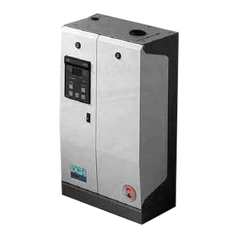
- Page 1 Installation & Maintenance Electronic Manual Steam Humidifiers Read and Save these Instructions...
- Page 2 How The SD 2000 Works The SD 2000 humidifier is what is called an “electrode” humidifier. This means that instead of heating elements, metal electrodes are immersed in water contained in a plastic cylinder. When steam is required for humidification, electric current flows through the water between the electrodes.
-
Page 3: Table Of Contents
PC-301 Air Proving Switch ......................41 WARNING: Your humidifier requires water to operate. Do NOT mount it above materials or machinery that could be damaged if a leak occurs. Carel assumes no responsibility for consequential or inconsequential damage as a result of any leaks. - Page 4 Installation & Maintenance Manual Your SD 2000 steam humidifier will consist of: Steam humidifier unit Steam distributor pipe(s) or Room Distribution Unit (blower) Steam hose & condensate hose, hose clamps Mounting bracket, mounting hardware and water fill quick connect fitting...
-
Page 5: General Installation Rules
Carel USA 1. General Installation Rules Mount the humidifier unit as close to the steam distributor pipe or Remote Distribution Unit as possible to minimize condensate. Mount the humidifier unit below the steam distributor pipe or RDU whenever possible. Insure that a slope can be maintained in the steam hoses. -
Page 6: Mount Steam Humidifier
Installation & Maintenance Manual 2. Mount Steam Humidifier Sizes and Weights UNIT MODEL NUMBER: DIMENSIONS AND WEIGHTS FACTOR C – HEIGHT 22.5” 25.2” 22.5” 25.2” 34” 34” 34” A – WIDTH 13” 14.2” 13” 14.2” 24.5” 40.25” 56” B – DEPTH 7.5”... -
Page 7: Position Of Steam Outlets
Carel USA 2.1. Position of Steam Outlets UNIT MODEL NUMBER: DIMENSIONS DIMENSION 3.2” 3.2” 3.2” 3.2” 4.1” 3.2” 4.1” 6.7” 6.7” 6.7” 12.2” 12.2” 3.7” 4.3” 3.7” 4.3” 5.7” 5.7” 5.7” NOTE: Allow clearance on the top of the humidifier for the steam hoses to exit and travel to their duct distributor pipes (if used). -
Page 8: Connect Plumbing
The water feed connection is a 3/4” MPS male connection on the bottom of the humidifier (2 on SD360 & 384 models, 3 on SD3B3). Carel supplies a plastic adapter that screws onto the fill fitting and gives a 1/4” OD compression fitting for plastic or copper tubing. -
Page 9: Connect Power Wiring
Each SD humidifier is internally wired for the maximum amperage that it can see on any voltage. Electrical wiring sizes must match all national and local electrical codes. Generally, the following maximum wire sizes can be... -
Page 10: Connect Control Wiring
5.2. Controls Wiring The SD humidifier controllers are preprogrammed from the factory to operate either as On/Off (CDC), Proportional from a control signal (CDP), or Proportional from a sensor input (CDH, CDD). Wiring the CDC On/Off Controller:... - Page 11 24 Vac/dc at 1 Amp. There is also a CDT controller that reads a temperature sensor input and controls the SD humidifier for use in a Turkish bath. It is wired the same was as the CDH controller, but with a temperature sensor instead.
-
Page 12: Install Steam Distributor Pipes
Installation & Maintenance Manual 6. Install Steam Distributor Pipes If your SD 2000 humidifier was supplied with duct steam distributor pipes, they must be mounted completely level in the duct with the steam outlet holes facing up as shown to the right. -
Page 13: Install Steam Hoses
Nothing must impede the free flow of either steam to the distributor pipes or condensate back to the SD unit or the drain. If Copper tubing is used, use two 45° angles or sweeping elbows rather than sharp 90° elbows. -
Page 14: Install Room Distribution Unit
Installation & Maintenance Manual 8. Install Room Distribution Unit Models SD101-313: If your SD 2000 humidifier was supplied with a direct mount RDU (Room Distribution Unit), it will have been shipped in place, ready to go. Simply mount the humidifier unit on the wall per the instructions in Section 2 and proceed to the unit wiring instructions. - Page 15 Carel USA Models SD323-3B3: The VRDXL used on the SD323-3B3 units is only available as a remote unit (wall mounting bracket supplied), although it can be mounted on the wall directly over the humidifier unit if desired. (2 VRDXL units are required for models SD360-384 and 3 are required for the SD3B3).
-
Page 16: Start Up And Check Out Of The Sd 2000 Humidifier
Installation & Maintenance Manual 9. Start up and Check out of the SD 2000 Humidifier Startup Checklist: 1. Water and drain lines are connected properly. Drain lines are trapped per Section 3. Fittings are tight. NOTE: Inlet water pressure must be between 15 and 150 psi. If higher than 150 psi, install regulator. -
Page 17: Operating The Sd 2000 Humidifier Controller
10. Operating The SD 2000 Humidifier Controller The SD 2000 controllers all have the same general display and keypad as shown below. Initially, the CDC and CDP controllers default to display of the amperage, while the CDH and CDD controllers default to display of the relative humidity. - Page 18 Installation & Maintenance Manual CDP 303: control is modulating. The controller has an input for an external modulating signal from a proportional humidity controller or DDC system. The input signal can be selected by the dip-switches located on the back of the controller.
-
Page 19: Display Sequence
Carel USA Pressing the SEL button 10.2. Display Sequence brings up the display screens in sequence Starting Display allowing the viewing of Appears for 2 seconds on startup. information and changing of 1. Mod parameters. Parameters that 2. Humidifier model number are changed take effect on 3. - Page 20 Installation & Maintenance Manual Drain Selection Press to change parameter: Cd = drain with electrodes under power td = drain without power (timed) Differential Setting (on CDH, CDD, CDT controllers only) 1. diF 2. Differential value Set Point Setting (on CDH, CDD, CDT controllers only) 1.
-
Page 21: Maintaining Your Sd 2000 Humidifier
11. Maintaining Your SD 2000 Humidifier Although your SD 2000 humidifier is designed to take care of its normal operation, and even to provide you with diagnostic capability, good operation always means good maintenance. Periodic cleaning or replacement of the steam generating cylinder, and fill and drain valves is required as indicated by the controller with an E08 alarm. - Page 22 Installation & Maintenance Manual To clean the fill and drain valves: After shutdown and removal of the steam cylinder, shut off the water supply to the humidifier, disconnect the water supply and remove the fill valve from the humidifier. Remove the inlet strainer by reaching up into the fill valve inlet with a pair of needle nose pliers and pulling out the strainer by its tab.
-
Page 23: Optimizing Cylinder Life On The Sd 2000 Electrode Steam Humidifier
13 in this manual. (10% cause) Short cycling of the humidifier due to oversizing. The SD must hit 5 fill cycles before it will decide to activate drain cycles. Correction to this is to limit the maximum production of the unit to match the load. -
Page 24: Trouble Shooting
Installation & Maintenance Manual 12. Trouble Shooting The SD 2000 electronic controller contains the most advanced diagnostics available on any electrode humidifier. Whenever there is an alarm or pre-alarm condition, a cursor appears on the left of the LCD display pointing to ALARM. - Page 25 Carel USA E06 CURRENT TOO HIGH: When amperage exceeds the second safety threshold. Causes: 1. Mineral bridge between electrodes. 2. Leakage of fill valve. 3. Blocked drain valve. 4. Back pressure from improper steam hose installation or duct. 5. TDO setting between 0 & 120.
- Page 26 Installation & Maintenance Manual E11 HIGH HUMIDITY: (In CDD models only) Causes: 1. Humidity has exceeded the high limit alarm setpoint. Remedies: 1. Check control circuit. 2. Check calibration of humidity sensor. 3. Raise hi-limit setpoint. E12 LOW HUMIDITY: (In CDD & CDH models only) Causes: 1.
- Page 27 Carel USA WATER IN THE CYLINDER TURNS BLACK: Causes: 1. This is usually an indication that the minerals in the cylinder have overconcentrated and the pH of the water has dropped causing a deterioration of the electrodes. Left unchecked, this will lead to a very short cylinder life.
- Page 28 Installation & Maintenance Manual HUMIDIFIER CONTINUOUSLY FILLS AND DRAINS WITHOUT PRODUCING STEAM: Causes: 1. Mineral has bridged between the electrodes. 2. There is back pressure from the steam hoses or duct. 3. The flow regulator in the fill valve is broken or out of place. 4.
- Page 29 Carel USA POWER CONTACTOR CHATTERS: Causes: 1. Installation dirt has gotten into the contactor and is interfering with its free movement. 2. Secondary voltage is too low. 3. Controller triacs are weak or damaged. Remedies: 1. Clean out the contactor or replace it.
-
Page 30: Replacement Parts
Installation & Maintenance Manual 13. Replacement Parts... - Page 31 Replacemnt electrodes for H400TA ADAH400TA0 Adaptor from K400TA to H400TA ADAK400TA0 Adaptor from H400TA to K400TA Cleanable Steam Cylinders: F200MA000C Cleanable cylinder for SD/OEM-101,102,103 F400TA000C Cleanable cylinder for SD/OEM-303,305 E401TA000C Cleanable cylinder for SD/OEM-308,313 KITF200MAC Replacement electrodes for F201MA000C KITF400TAC...
- Page 32 Preformed Pipe (Large) 1312345AXX Preformed Pipe (MS) 1312346AXX Preformed Pipe (MS) KITTC00000 Preformed Pipe (SD323,333,342,360(2),384(2),3B3(3)) 13C119A003 Fill Cup (SD 101,102,103,106,303,305,308,313), Ser. #<20000 13C119A003 Fill Cup (SD 101,102,103,303,305), Ser. #>20000 KITVCCN000 Fill Cup (SD 106,308,313), Ser. #>20000 KITCN00000 Conductimeter (SD323,333,342,360,384,3B3) KITTS50001...
- Page 33 Carel USA...
- Page 34 Installation & Maintenance Manual...
- Page 35 Carel USA...
- Page 36 Installation & Maintenance Manual...
- Page 37 Carel USA...
-
Page 38: Technical Specifications
Installation & Maintenance Manual Technical Specifications UNIT MODEL NUMBER: CAPACITY, AMPERAGE, WATTAGE FACTOR LBS/HR AMPS 11.2 24.0 WATTS 1666 2333 5000 LBS/HR AMPS 10.6 22.7 WATTS 1666 2333 5000 LBS/HR AMPS 20.8 WATTS 1666 2333 5000 LBS/HR AMPS 10.2 18.5 27.7 46.9 69.1... -
Page 39: Aswh / Asdh - Asdh / Asdc Wall - Duct Temperature/Humidity Sensors
Carel USA 14.1. ASWH / ASDH – ASDH / ASDC Wall – Duct Temperature/Humidity Sensors Model Description Temperature: NTC thermistor, 10 Kohm at 25°C (77°F) (ASWC/ASDC only) Humidity (0-1 VDC or 4-20 mADC) Accuracy: +- 0.25°C from 0 to 50°C (32 to 122°F) -
Page 40: Hc-101 And Hc-201 Wall And Duct Humidistats
Installation & Maintenance Manual 14.2. HC-101 and HC-201 Wall and Duct Humidistats Mounting the HC-101 room humidistat: Mount the HC-101 humidistat to an inside wall or post in the area to be humidified. Position it so that no drafts from registers or outlets are blowing on it. Be sure that it is not placed over a device that could generate heat or vapor ie: stove, machinery, cleaning vat. -
Page 41: Pc-301 Air Proving Switch
Carel USA 14.3. PC-301 Air Proving Switch Mounting the PC-301 air flow switch: Mount the airflow switch in the supply or return duct using the screws supplied. Mount the device so that the diaphragm is in a vertical position as shown at right. - Page 42 Installation & Maintenance Manual Condensate Pumps 14.4. HUMIDIFY ON ALARM RESET DRAIN CAREL CAREL USA Title: SD CONDENSATE INSTALLATION Approved By: Created By: BGK Scale: Date: Date: 08/30/01 Material: FILENAME: CP-SA-SD CONDENSATE INSTALL-00...
- Page 43 Carel USA NOTES:...
- Page 44 Installation & Maintenance Manual Form: +03U400125 Rev. 0.0...
Need help?
Do you have a question about the SD and is the answer not in the manual?
Questions and answers