Sign In
Upload
Manuals
Brands
AMETEK Manuals
Power Supply
Sorensen SGI Series
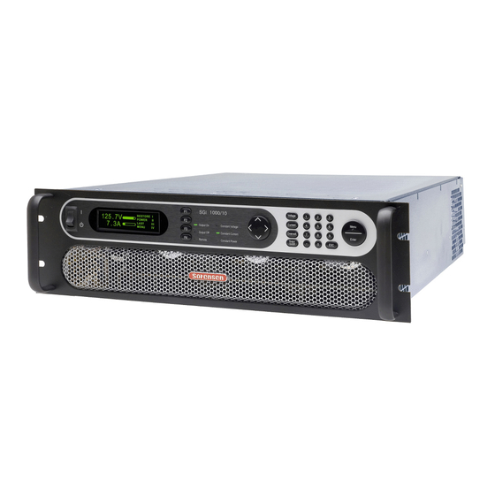
AMETEK Sorensen SGI Series Manuals
Manuals and User Guides for AMETEK Sorensen SGI Series. We have
1
AMETEK Sorensen SGI Series manual available for free PDF download: Operation Manual
AMETEK Sorensen SGI Series Operation Manual (120 pages)
Brand:
AMETEK
| Category:
Power Supply
| Size: 6.2 MB
Table of Contents
Contact Information
3
Important Safety Instructions
5
Safety Symbols
6
Fcc Notice
7
About this Manual
8
Table of Contents
9
Section 1 Overview
15
General Description
15
Figure 1-1. Model Number Decoding
16
List of Figures
16
Specifications
17
Environmental Characteristics
17
Electrical Characteristics
17
SGI Series Voltage and Current Specifications
21
Physical Characteristics
22
Section 2 Installation
23
Inspection
23
Contents of Shipment
23
Location and Mounting
24
Rack Mounting
25
Chassis Removal from Rack
25
Input/Output Connections
26
Table 2-1. Maximum AC Current Ratings, PFC Models
27
Table 2-2. Maximum AC Current Ratings, Non-PFC Models
27
Table 2-3. Input/Output Connectors
27
Table 2-4. Input Terminal Connections
28
Table 2-5. Output Terminal Connections
28
Table 2-6. Recommended Lugs
28
Table 2-7. Recommended Sense Connector Tools
28
Wire Selection
29
Wire Size
29
Table 2-8. Minimum Wire Size
29
Table 2-9. Wire Resistance and Voltage Drop, 20°C
31
Load Considerations
32
Inductive and Stored-Energy Loads
32
Figure 2-1. Diode Connection
32
Outline Drawings
33
Figure 2-2. Installation Drawing, 3U Models 10V-30V
34
Figure 2-3. Installation Drawing, 3U Models 40V-600V
35
Figure 2-4. Installation Drawing, 3U Models 800V and 1000V
36
Figure 2-5. Installation Drawing, 6U Models 20Kw-30Kw
37
Figure 2-6. Rear Panel, Standard, 3U Models 10V-30V
38
Figure 2-7. Rear Panel, GPIB Option, 3U Models 10V-30V
39
Figure 2-8. Rear Panel, Ethernet Option, 3U Models 10V-30V
40
Figure 2-9. Rear Panel, Standard, 3U Models 40V-600V
41
Figure 2-10. Rear Panel, GPIB Option, 3U Models 40V-600V
42
Figure 2-11. Rear Panel, Ethernet Option, 3U Models 800V and 1000V
43
Figure 2-12. Rear Panel, Standard, 6U Models 20Kw-30 Kw
44
Figure 2-13. Rear Panel, GPIB Option, 6U Models 20Kw-30 Kw
45
Figure 2-14. Rear Panel, Ethernet Option, 6U Models 20Kw-30 Kw
46
Figure 2-15. Instructions for Assembly of AC and DC Covers
47
Section 3 Operation
49
Introduction
49
Front/Rear Panels
49
Figure 3-1. Front Panel Controls and Indicators (3U Model Shown)
49
Table 3-1. Front Panel Controls and Indicators
50
Figure 3-2. Rear Panel Interface, Standard, 3U Models 10V-30V
51
Figure 3-3. Rear Panel Interface, GPIB Option, 3U Models 10V-30V
51
Figure 3-4. Rear Panel Interface, Ethernet Option, 3U Models 10V-30V
51
Figure 3-5. Rear Panel Interface, Standard, 3U Models 40V-600V
52
Figure 3-6. Rear Panel Interface, GPIB Option, 3U Models 40V-600V
52
Figure 3-7. Rear Panel Interface, Ethernet Option, 3U Models 800V and 1000V
52
Figure 3-8. Rear Panel Interface, Standard, 6U Models 20Kw-30Kw
53
Figure 3-9. Rear Panel Interface, GPIB Option, 6U Models 20Kw-30Kw
53
Figure 3-10. Rear Panel Interface, Ethernet Option, 6U Models 20Kw-30Kw
53
Table 3-2. Rear Panel Connectors and Controls, Standard
54
Table 3-3. Rear Panel Connectors and Controls, GPIB Option
55
Table 3-4. Rear Panel Connectors and Controls, Ethernet Option
56
Basic Operation and Output Verification
57
Initial Setup
57
Default Programming Menu
57
Constant-Voltage Mode Operation
58
Constant-Current Mode Operation
59
Overvoltage Protection
60
Initial Start-Up Displays
61
Display Elements
62
Navigation
63
Editing
64
Aborting an Edit
65
Menu Map
66
Home Menu
66
Default Programming Menu
66
Navigating from Home Menu
66
Navigating from Home Menu
67
Sequence Menu
68
Sequence Programming Operation
68
Constant-Power Setup Menu
69
Remote Menu
69
3.7.10 Remote Control Screen Examples
70
3.7.11 Warning Screens
70
3.7.12 Other Screens
70
Programming/Operating Functions
70
Voltage, Current, and Overvoltage Protection Programming
70
Save
71
Recall
72
Sequencing
73
Figure 3-11. Burn-In Sequence Example
78
Constant-Power Mode
81
Figure 3-12. Constant-Power Example
81
Home Timeout
82
Display Brightness
82
Lock Key
82
Language
82
3.8.10 Info
83
3.8.11 Remote
83
3.8.12 System
86
3.8.13 Warning Screens
87
Remote Analog Control Connector (J1)
87
Figure 3-13. Analog Control Connector (J1) Pin-Out
88
Table 3-5. Analog Control Connector (J1), Designations and Functions
90
Remote Current Programming
91
3.10.1 Remote Current Programming by Resistance
91
Figure 3-14. Remote Current Programming Using Resistance
91
3.10.2 Remote Current Programming by Voltage Source
92
Figure 3-15. Remote Current Programming Using 0-5 VDC or 0-10 VDC Source
92
Remote Voltage Programming
93
3.11.1 Remote Voltage Programming by Resistance
93
Figure 3-16. Remote Voltage Programming Using Resistance
93
3.11.2 Remote Voltage Programming by Voltage Source
94
Figure 3-17. Remote Voltage Programming Using 0-5 VDC or 0-10 VDC Source
94
Remote Overvoltage Programming
95
Figure 3-18. Remote Overvoltage Programming Using DC Voltage Source
95
Remote Output On/Off Control
96
Remote Output ON/OFF by Contact Closure
96
Remote Output ON/OFF Control by External Source
96
Figure 3-19. Remote Output On/Off Control by Contact Closure
96
Remote Shutdown(S/D)
97
Figure 3-21. Remote Output On/Off Using Isolated TTL/CMOS Source
97
Figure 3-22. Remote Shutdown Using DC Voltage Source
97
Remote Sensing
98
Figure 3-23. Remote Voltage Sensing Network
98
Figure 3-24. Remote Sense Connection at the Load, 10V-800V Models
99
Figure 3-25. Remote Sense Connection at the Load, 1000V Model
100
Floating and Polarized Output
101
Parallel and Series Operation
102
3.16.1 Parallel Operation
102
Figure 3-26. Parallel Connection and Remote Sense
103
3.16.2 Series Operation
104
Section 4 Calibration and Verification
105
Introduction
105
Calibration and Verification Cycle
105
Preparation
105
Calibration and Verification Procedures
106
Constant-Current Mode
107
Constant-Voltage Mode
107
Resistive-Control Programming Current Sources
108
Change Calibration Date
109
Remote Isolated Analog Interface (Option) Calibration and Verification Procedure
109
Constant-Current Mode
109
Constant-Voltage Mode
110
Change Calibration Date
111
Figure 4-1. Potentiometer Locations
112
Section 5 Maintenance
113
Introduction
113
Preventive Maintenance
113
Fuses
115
Table 5-1. Fuse Ratings
115
Advertisement
Advertisement
Related Products
Ametek Sorensen SGA Series
Ametek Sorensen SGA Series DC
Ametek Sorensen SG Series
Ametek Sorensen DHP Series
Ametek Sorensen XTR
Ametek Sorensen XPH Series
Ametek Sorensen Asterion AST Series
Ametek Sorensen DCS-E Series
Ametek Sorensen XHR Series
Ametek Sorensen Asterion DC
AMETEK Categories
Measuring Instruments
Test Equipment
Power Supply
Controller
Laboratory Equipment
More AMETEK Manuals
Login
Sign In
OR
Sign in with Facebook
Sign in with Google
Upload manual
Upload from disk
Upload from URL