Extron electronics PVS 407D User Manual
Polevault digital switcher
Hide thumbs
Also See for PVS 407D:
- Installation manual (81 pages) ,
- User manual (72 pages) ,
- Setup manual (4 pages)

Related Manuals for Extron electronics PVS 407D


Summary of Contents for Extron electronics PVS 407D
- Page 1 User Guide PoleVault Switchers PVS 407D PoleVault Digital Switcher 68-2776-01 Rev. B 10 18...
- Page 2 Safety Instructions Safety Instructions • English Istruzioni di sicurezza • Italiano AVVERTENZA: Il simbolo, , se usato sul prodotto, serve ad WARNING: This symbol, ,when used on the product, is avvertire l’utente della presenza di tensione non isolata pericolosa intended to alert the user of the presence of uninsulated dangerous all’interno del contenitore del prodotto che può...
- Page 3 “Extron Safety and Regulatory Compliance Guide” on the Extron website. Copyright © 2015-2018 Extron Electronics. All rights reserved. www.extron.com Trademarks All trademarks mentioned in this guide are the properties of their respective owners. The following registered trademarks ( ®...
- Page 4 Conventions Used in this Guide Notifications The following notifications are used in this guide: WARNING: Potential risk of severe injury or death. AVERTISSEMENT : Risque potentiel de blessure grave ou de mort. ATTENTION: • Risk of property damage. • Risque de dommages matériels. NOTE: A note draws attention to important information.
-
Page 5: Table Of Contents
Installing the Software ........36 Labeling the AV Inputs ........7 Installation ............ 36 Labeling the PVT Faceplates ......7 Starting the PVS 407D Product Configuration Final Setup ............. 8 Software ............37 Securing the HDMI Cable ........8 New Configuration File ........38 Open Configuration File ........ - Page 6 RS-232 Connector Wiring ........ 77 Configure This Device Panel ......69 Wiring for IR Communication ......78 Passwords Panel .......... 70 Input 7 Connector Wiring ........80 Date/Time Settings Panel ......71 Downloading the Latest Switcher Firmware ..72 PVS 407D Switcher • Contents...
-
Page 7: Introduction
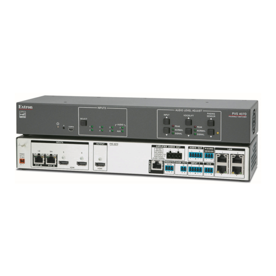
ONLY, as supplied by Extron. PVS 407D Description The Extron PVS 407D is part of the PoleVault System and is used in conjunction with the Extron PVT series of transmitters and Extron speakers. It has four video and audio twisted pair inputs, two HDMI inputs, and one HDMI output, and incorporates a built-in audio amplifier. -
Page 8: Inputs
Priority Page Sensor. A third dedicated port allows the user to connect an auxiliary audio device. Outputs The PVS 407D has one HDMI output, an amplified audio output, and a line out audio output for assistive listening or recording devices. Control and Configuration... -
Page 9: Application Diagram
M LC 4 IP P LU Blu-ray Player Extron MLC 104 IP Plus Extron MediaLink Controller VLM 3002H VoiceLift Pro Pendant, Handheld, and Charging Station Legend: Video Audio Control CATx Figure 1. Typical PVS 407D Application PVS 407D Switcher • Introduction... -
Page 10: Rear Panel Connections
Rear Panel Connections This section describes cable connections to a PVS 407D switcher. NOTE: This equipment is to be connected only to networks without routing to the outside plant. Rear Panel Connectors PVS 407D OUTPUT AMPLIFIED AUDIO OUT AUDIO OUT... -
Page 11: Outputs
— Connect speakers to this 5 mm captive screw 4-pole connector. The amplified audio is capable of outputting 50 watts (2 x 25 watts RMS) for 4 and 8 ohm speakers (see Speaker Configuration, page 71, for wiring details). PVS 407D Switcher • Rear Panel Connections... -
Page 12: Control Ports
Use only the supplied 12 V, 4 A or 12 V, 4.2 A power supply for this switcher. • The PVS 407D power supply can support a typical system: for example, a PVS 407D, 2 PVT Wallplates, 2 or 4 speakers, an MLC 104 IP Plus with an IRCM DV+, and a VoiceLift Microphone system. Grounding stud —... -
Page 13: Labeling The Av Inputs
Repeat step 1 for the other end of the cable, using the same label type. Using the correct label type, repeat steps 1 and 2 as necessary for all signal cables that are to be connected to the PVS 407D. Connect the designated input cable to the corresponding input. -
Page 14: Final Setup
The supplied Extron LockIt HDMI cable lacing bracket makes it possible to secure a standard HDMI cable to the PVS 407D switcher. To securely fasten an HDMI cable to the PVS 407D (see image at right): 1. Plug the HDMI cable into the rear panel HDMI connector 2. -
Page 15: Operation
Operation This section of the manual discusses the operation of a PVS 407D device. Topics covered include: • Front Panel Overview Configuration • • Resetting the Switcher Executive Mode (Front Panel Security Lockout) • • Power Save Modes • Setting Up and Optimizing the Audio... -
Page 16: Front Panel Operation
On initial switcher power-up the volume level is SIGNAL Signal threshold; automatically adjusted to 80%. raise input gain. • To adjust paging sensitivity, press the sensitivity buttons Paging Sensor increase or decrease sensitivity (default setting is 50). PVS 407D Switcher • Operation... -
Page 17: Configuration
Configuration The PVS 407D switcher can be controlled by a MediaLink Controller (MLC) or by an RS-232 device acting through the MLC. Alternatively, the switcher can be set up and controlled via a host computer or other device (such as a control system) attached to the front panel USB connector or direct connection to the Ethernet, or to the rear panel RS-232 remote port of the switcher. -
Page 18: Front Panel Security Lockout (Executive Mode)
This mode can also be turned on or off through PCS software, TCP/IP, USB, or RS-232 control. For details, see SIS Communication and Control section, starting at page 18, or Using the Extron Product Configuration Software section, starting on page 36. PVS 407D Switcher • Operation... -
Page 19: Power Save Modes
Power Save Modes The PVS 407D is an ENERGY STAR qualified device, and has five Power Save modes, ® (see table below for mode descriptions). See the relevant SIS commands on page 24. Mode Type Activation Device and Wake-up trigger... -
Page 20: Setting Up And Optimizing The Audio
Refer to the transmitter user guide for installation and connection information. Ensure a set of speakers is connected to the PVS 407D. Adjust the input gain level for one input through the front panel or by configuration... -
Page 21: Gain Control
Individual gain adjustment can also be made by configuration software. Repeat the steps for the other inputs as desired. NOTE: The Peak, Normal, and Signal LEDs function as the Aux Input level indicator only when the switcher is in the “Aux Adjust” mode. PVS 407D Switcher • Operation... -
Page 22: Bass And Treble Control
NOTE: If output audio is muted via the 1Z SIS command, all embedded audio on the HDMI, line out and amplifier outputs is not be heard. The VoiceLift Microphone input can be muted via a separate SIS command (see the SIS Communication and Control section, page 18, for details). PVS 407D Switcher • Operation... -
Page 23: Paging Sensitivity Adjustment
This is to prevent the audio being un-muted if the announcer pauses or stops talking while making the announcement or page. PVS 407D Switcher • Operation... -
Page 24: Sis Communication And Control
Switcher-Initiated Messages When a local event such as a front panel selection or adjustment takes place, the PVS 407D responds by sending a message to the host. No response is required from the host. Example switcher-initiated messages are listed here. -
Page 25: Error Responses
ASCII (Telnet) and URL encoded (Web). NOTE: Upper and lower case text can be used interchangeably unless otherwise stated. ASCII to HEX Conversion Table space • Figure 12. ASCII to Hexadecimal Character Conversion Table PVS 407D • SIS Communication and Control... -
Page 26: System Definitions
Audio input 1-7 = Active Program (post switch) put rate) 8 = VoiceLift 9 = Aux PVS 407D must have firmware version 2.00 or greater for NOTE: 10 = Embedded HDMI audio out 4K/UHD support on all HDMI inputs. Audio status... - Page 27 X10! Default name Combination of model name and last X11# Prefix (subnet Subnet 255.255.0.0 is represented 3 hex pairs of MAC address mask bits) as a prefix value by /16. (for example PVS-407D-07-4B-E9) PVS 407D • SIS Communication and Control...
- Page 28 Default analog EDID for Firmware version 4.00 or below Default digital EDID for Firmware version 3.00 or above NOTE: PVS 407D must have firmware version 2.00 or greater for 4K/UHD support on all HDMI inputs. PVS 407D • SIS Communication and Control...
-
Page 29: Command And Response Tables
Set volume to X3%. Increment Increase volume. Decrement Decrease volume. View volume View current volume setting. Verbose mode 2/3 NOTE: = Audio output volume 000 to 100, (-100 dB to 0 dB), [default 080] PVS 407D • SIS Communication and Control... - Page 30 View Aux input Signal, Normal, View Aux input audio Signal, Normal, •Norm •Clp and Peak status and Peak status. Verbose mode 2/3 Sts 05*Sig • Norm •Clp KEY: = Status 0 = Off/disable 1 = On/enable PVS 407D • SIS Communication and Control...
- Page 31 Export EDID file X1*] Export EDID from specified Edid E EDID slot to <filename>. <filename>EDID Send file from unit to PC file data(128 or 256 bytes) Send <filename> from unit to PC. <filename>SF PVS 407D • SIS Communication and Control...
- Page 32 Set HDMI output sync mode to View output sync mode X1%] View HDMI output sync mode. MSSAV Verbose mode 2/3 X1%] Ssav M = HDMI output sync mode = Disable output sync (default) KEY: = Enable output sync PVS 407D • SIS Communication and Control...
- Page 33 Set horizontal start value E X2( X3@] HSRT} Hsrt Set horizontal start at Increment horizontal start X3@] Increase horizontal start to HSRT} Hsrt value Decrement horizontal start X3@] HSRT} Hsrt Decrease horizontal start to value PVS 407D • SIS Communication and Control...
- Page 34 = VoiceLift microphone status 0 = No carrier/ microphone is off 2 = Channel B or D 1 = Channel A or C 3 = Channels A or C and B or D PVS 407D • SIS Communication and Control...
- Page 35 0 = LINK slot 2 is not paired or pairing fails. 1 = LINK slot 2 is paired to a microphone. 9 = Microphone is on/ connected or LINK slots are occupied and cannot pair. PVS 407D • SIS Communication and Control...
- Page 36 Set Line out to variable Where 1 = variable (default). 55*1# LineOut*1 Set Line out to fixed Where 2 = fixed. 55*2# LineOut*2 View Line out mode Where X = 1 (variable, default), LineOut*X or 2 (fixed). PVS 407D • SIS Communication and Control...
- Page 37 # Bytes Used out of # KBytes] Inf04*# Bytes Used out of Verbose mode 2/3 # KBytes] Query firmware version x.xx] View firmware version. Query full firmware version x.xx.xxxx] View full firmware version. PVS 407D • SIS Communication and Control...
- Page 38 EDID settings, image captures, user-supplied HTML files, and so forth. Space being used by firmware for internal operations (such as saving of non-volatile settings) is not removed. Absolute system reset See Note below. Zpq] ZQQQ} NOTE: This command resets all device settings to factory default; however, firmware version remains the same. PVS 407D • SIS Communication and Control...
- Page 39 E X10( • X10(] X10( Set the IP address to Read IP address View the current IP address. X10(] X10& KEY: = On/Off status 0=off/disable; 1=on/enable X10( xxx.xxx.xxx.xxx 192.168.254.254 = IP address = default) PVS 407D • SIS Communication and Control...
- Page 40 Read MAC address X10$] 00-05-A6-xx-xx-xx Verbose mode 2/3 • X10$] View number of Ethernet X4$] View the number of open connections. connections KEY: = Number of open connections X10$ = Hardware MAC address (00-05-A6-xx-xx-xx) PVS 407D • SIS Communication and Control...
- Page 41 Passwords are case-sensitive and cannot be a single space. • User password cannot be assigned if no admin password exists, (returns E14). • If admin password gets cleared, then user password is removed too. PVS 407D • SIS Communication and Control...
-
Page 42: Using The Extron Product Configuration Software
Software The Extron PVS 407D Product Configuration Software (PCS) offers another way to control the PVS 407D via USB connection or Ethernet Connection, in addition to using the SIS commands. This section describes installation and gives a basic overview of the software. -
Page 43: Starting The Pvs 407D Product Configuration Software
New Configuration File tab, by clicking on the drop-down arrow. This opens two menu options: New Configuration File and Open Configuration File. Figure 14. New or Open Configuration File menu Choose either New Configuration File or Open Configuration File. PVS 407D • Using Extron Product Configuration Software... -
Page 44: New Configuration File
Figure 16. Device Input Configuration Page. NOTE: The PVS 407D tab (top left) has a gray connection status indicator (circle) that indicates there is no actual device connected and the software is running in emulation mode. When an item on a menu screen is grayed out, that item is not selectable at that time and may only be selectable when in a live (connected) mode. -
Page 45: Open Configuration File
.extc file previously saved on the connected PC. Figure 17. Select the Saved Configuration File. Click Open. This opens in offline configuration (emulation mode) and the PVS 407D device input configuration screen appears (see figure 16 on previous page). -
Page 46: Connect To A Device
If a device is not connected, the Disconnect, Reset, and Update Firmware options are disabled until the device is connected. PVS 407D Help File — Opens the device specific Help file. This file opens in a browser and has an embedded PDF file for printing if desired. - Page 47 If applicable, enter the password of the connected MLC. Enter the Telnet Port for the connected MLC (default is 23). Enter the Pass-Thru Port number for the connected MLC (default is 2003). Figure 20. Example Connection via Pass-Thu Option PVS 407D • Using Extron Product Configuration Software...
- Page 48 For a device not listed but where the IP address is known: Click the TCP/IP tab. Enter the IP address of the PVS 407D. If applicable, enter the password of the device. When checked, the Show Characters check box allows the user to see the password letters when typed Enter the Telnet port for the device (default is 23).
-
Page 49: Deploy Configuration To Devices
PVS 407D switchers simultaneously over the network either via direct connection to the PVS 407D or MLC pass-thru port. In addition it allows the user to save a list of added devices as a manifest file (.mfst extension). This manifest file can be imported for later use without the need to manually reenter details for each device (IP, password and port settings). - Page 50 Click the Deploy button. The deployment begins, and the window initially updates with the status of the deployment as Deploying or Pending. A progress bar, at top left, graphs the deployment percentage completed. PVS 407D • Using Extron Product Configuration Software...
- Page 51 (see in the figure below). This allows the user the re-deploy the configuration again after making any necessary corrections to the device connection status. Figure 26. Errors Observed in the Deployment Process PVS 407D • Using Extron Product Configuration Software...
- Page 52 When deployment is completed click Close. If the list has not been saved, you are prompted to save the list. See Saving and Opening the List of Target Devices section in the PCS-PVS 407D Help file embedded in the PCS software for full details. PVS 407D • Using Extron Product Configuration Software...
-
Page 53: Using Pcs - Panel And Pages
The AV Controls panel, which can be hidden when not needed, and the four pages (Input Configuration, EDID Minder, Audio Config, and General Settings) are used for configuring the PVS 407D. AV Controls Panel The AV Controls panel is used to control AV settings such as input selection or muting video and audio signals. -
Page 54: Configuration Pages
HDCP Authorized device. If the box is not checked the source is blocked from encrypting its output. This may result in some content not being passed to the output. NOTE: The HDCP Authorized is only available for HDCP inputs. PVS 407D • Using Extron Product Configuration Software... -
Page 55: Edid Minder Page
From this page an EDID data set can be assigned to any input with an RGB or an HDMI or DVI input type. The currently assigned EDID properties can be viewed and EDID files can be loaded to and from the PVS 407D. Figure 31. - Page 56 Click the Assign to All button. NOTE: If you select Assign to All, all input boxes, checked or unchecked, are ignored and the EDID is assigned to all inputs. PVS 407D • Using Extron Product Configuration Software...
-
Page 57: Audio Configuration Page
For each input that has a gain value, when the input is selected, the current gain value is updated and displayed. • The input gain setting is also available for adjustment when you are configuring the PVS 407D offline. PVS 407D • Using Extron Product Configuration Software... - Page 58 The Peak, Normal, or Signal LEDs light when each threshold is reached as the input gain is adjusted (see X% on page 20 for signal thresholds). PVS 407D • Using Extron Product Configuration Software...
- Page 59 In addition the device list can be exported as a .csv file, that can be opened and saved in Excel or Notepad, or a similar program. ® PVS 407D • Using Extron Product Configuration Software...
- Page 60 To rename an audio files in the library: Select and right-click on an audio file, and select Rename from the pop-up menu. Figure 36. Audio Files Management in the Library PVS 407D • Using Extron Product Configuration Software...
- Page 61 To save an existing listed audio file to the audio library: Select an audio file on the device list and right-click. Select Save to Library from the drop-down menu. The file is saved to the audio library. PVS 407D • Using Extron Product Configuration Software...
- Page 62 To sync the device: Click Sync to Device (see figure 35 on page 54) to sync the device list on the connected PVS switcher. This allows the audio files to be played from the switcher. PVS 407D • Using Extron Product Configuration Software...
-
Page 63: Vlr 302 Config Page
Click the Reset Usage button. The Microphone Usage data shown on this page is reset. To reset the the VLR 302 device: Click the Reset VLR 3O2 button. The VLR 302 configuration is reset and all pairing and chime settings are set to default. PVS 407D • Using Extron Product Configuration Software... -
Page 64: General Settings Page
This page allows you to set the Front Panel lock mode and Auto Power Save mode for the PVS 407D. This page also allows you to access the device hardware settings by clicking on the Hardware Settings button (see the Hardware Settings section for details). -
Page 65: Hardware Settings
This gives a non-configurable view of information about the connected unit, and is divided into two sections. First section includes part numbers, model name and model description, firmware versions and build numbers for the switcher, connected wallplates and optional VoiceLift device. PVS 407D • Using Extron Product Configuration Software... - Page 66 Example Unit Information Panel - Second Section Device Name This panel allows the user to enter a name for the device or reset it to the default. Figure 44. Device Name Panel PVS 407D • Using Extron Product Configuration Software...
- Page 67 Click Apply at the bottom of the panel. The device is set to the newly inputted date and time. To sync date and time to a PC: Click Sync to PC. The date and time files update to match the synced PC. PVS 407D • Using Extron Product Configuration Software...
- Page 68 Click Apply at the bottom of the panel. The new password is saved. System Reboot This gives a user the ability to reboot the device by clicking Reboot. Figure 47. System Reboot Panel PVS 407D • Using Extron Product Configuration Software...
-
Page 69: Using Pcs - Software Menu
Information and details for using this menu are available in the Extron PCS Help file, opened by clicking on Extron PCS Help. This file opens in a browser and has an embedded PDF file for printing if desired. PVS 407D • Using Extron Product Configuration Software... -
Page 70: Using The Internal Web Page
Using the Internal Web Page The PVS 407D features an internal Web server that hosts an embedded web page. This page allows you to: • Edit the TCP/IP settings • Edit the device name Update the firmware version • •... -
Page 71: Turning Off Compatibility Mode
Be sure that the check box is Display all websites in Compatibility View cleared, and that the IP address of the PVS 407D is not in the list of Web sites that have been added to Compatibility view. Using the Internal Web Page... -
Page 72: Communication Settings Panel
The host name is generated from the device name, and it can only be changed in panel, or by using PCS or SIS commands. Device Info Figure 51. Communication Settings Panel - TCP/IP PVS 407D • Using the Internal Web Page... -
Page 73: Device Information Panel
This section displays details of the device name, part number, model name, model description, and firmware versions (for PoleVault switcher, wallplate 1 and wallplate 2). Part number, model name, and model description are read only. PVS 407D • Using the Internal Web Page... - Page 74 2, and allows the user to update the firmware to the switcher. NOTE: The latest firmware can be downloaded from the Extron website (see Downloading the Latest Switcher Firmware on page 70 for method). PVS 407D • Using the Internal Web Page...
-
Page 75: Configure This Device Panel
The link in this panel takes the user to the Extron website where the Product Configuration Software (PCS) can be located and then downloaded. After downloading, consult the software Help file (or see Using the Extron Product Configuration Software section in this guide) for configuration methods. PVS 407D • Using the Internal Web Page... -
Page 76: Passwords Panel
Click the Set button. The Passwords dialog box opens. Change each password field as applicable, and click Apply. The passwords are updated and the dialog box closes. Click Cancel at any time to exit the process without making any changes. PVS 407D • Using the Internal Web Page... -
Page 77: Date/Time Settings Panel
Choose the applicable time zone from the Time Zone list. Click Apply. The date and time changes are applied and the dialog box closes. Click Cancel at any time to exit the process without making any changes. PVS 407D • Using the Internal Web Page... -
Page 78: Downloading The Latest Switcher Firmware
Downloading the Latest Switcher Firmware The latest switcher firmware can be downloaded from the Extron web site and installed onto the hard drive of a connected PC, ready for uploading to the PVS 407D switcher. To download from the website: On the Extron website (www.extron.com), select the... -
Page 79: Connector Wiring
Connector Wiring This section of the manual discusses the connector wiring for a PVS 407D device. Topics covered include: Speaker Configuration • • TP Cable Termination and Recommendations Power Supply Wiring • • RS-232 Connector Wiring • Input 7 Connector Wiring... -
Page 80: Terminating The Speaker Cable
TP Cable Termination ATTENTION: • The PoleVault signal transmission method is specific for PVS 407D switchers working with PVT digital wallplates. DO NOT connect the input ports to an MTP system or to an Ethernet/LAN or data transmission system. •... -
Page 81: Power Supply Wiring
Power Supply Wiring NOTE: Use only the supplied 12 VDC, 4 A, or 4.2 A power supply for this switcher. The PVS 407D power supply can support a typical system: for example, a PVS 407D, 2 PVT Wallplates, 2 or 4 speakers, an MLC 104 IP Plus with an IRCM DV+, and a VoiceLift Microphone system. - Page 82 à vis. NOTE: Do not tin the power supply leads before installing them in the direct insertion connector. Tinned wires are not as secure in the connectors and could be pulled out. PVS 407D • Connector Wiring...
-
Page 83: Rs-232 Connector Wiring
RS-232 Connector Wiring Figure shows the wiring for the PVS 407D and the MLC 104 IP Plus RS-232 connectors. NOTE: The MLC 104 IP Plus is powered from the same supply used by the PVS 407D. REMOTE PVS 407D RS-232... -
Page 84: Wiring For Ir Communication
PROJECTOR CONFIG RS-232/IR CONFIG RS-232/IR MLC 104 IP Plus Figure 63. IR Emitter Cable Connection NOTE: Some projectors require null connection wiring, which inverts the Tx and Rx connections. See the projector guide for details. PVS 407D • Connector Wiring... - Page 85 IR control for a connected input device such as a Blu-ray player can be made through the PVT wallplate. The connections between the MLC 104 IP Plus and the PVS 407D switcher should look like the figure below. PVS 407D...
-
Page 86: Input 7 Connector Wiring
Sleeve Ring Balanced Audio Input Balanced Mono Input (high impedance) Sleeve Sleeve Sleeve Unbalanced Stereo Input Unbalanced Mono Input Audio Input 7 Audio Input Do not tin the wires! Figure 65. Input 7 Audio Wiring PVS 407D • Connector Wiring... - Page 87 Extron Electronics makes no further warranties either expressed or implied with respect to the product and its quality, performance, merchantability, or fitness for any particular use. In no event will Extron Electronics be liable for direct, indirect, or consequential damages resulting from any defect in this product even if Extron Electronics has been advised of such damage.
Need help?
Do you have a question about the PVS 407D and is the answer not in the manual?
Questions and answers