Table of Contents
Advertisement
Quick Links
Advertisement
Table of Contents

Related Manuals for Electrolux Hob


Summary of Contents for Electrolux Hob
- Page 1 SERVICE MANUAL COOKING Built-in hobs © ELECTROLUX ZANUSSI S.p.A. Publication GAS HOBS WITH Corso Lino Zanussi,30 number ELECTRONIC IGNITION I - 33080 PORCIA /PN (ITALY) 599 36 62-62 Tel +39 0434 394850 Fax +39 0434 394096 EN/SERVICE/FV Edition: 04.2005 SOI 04.05 FV...
- Page 2 SOI 04.05 FV 2/57 599 36 62-62...
-
Page 3: Table Of Contents
4.4.3 POWERED FLAME MODULATION VALVES..................20 Fig. 15................................21 4.4.4 MAIN SAFETY SOLENOID VALVE ..................... 22 POSITIONS OF THE COMPONENTS INSIDE THE HOB ..............23 OPERATING THE HOB (extract from Instruction Booklet) ............... 24 TOUCH CONTROL KEYS ........................24 LIGHTING THE BURNER........................24 SWITCHING OFF THE BURNERS...................... - Page 4 9.4.4 REPLACEMENT OF POWER BOARD....................50 9.4.5 – REPLACEMENT OF BURNERS....................... 51 9.4.6 REPLACEMENT OF THERMOCOUPLES ..................52 9.4.7 REPLACEMENT OF IGNITION SPARK PLUGS................. 54 ELECTRIC DIAGRAMS..........................55 10.1 BASIC ELECTRIC DIAGRAM ......................55 10.2 WIRING DIAGRAM ..........................56 10.3 KEY TO DIAGRAM..........................
-
Page 5: General Precautions
In order to avoid serious burns, it is important to ensure that no person touches the surface while the pilot lamp is lit. Do not switch on the burners without pans in the cooking areas, otherwise the hob may overheat and, after a time, the burner will switch off. -
Page 6: Introduction
S.O.E.C. control units. C.H.E.C. control units. KRONOS control units. Interface board of the Electronic gas hob. 1.3 GENERAL DESCRIPTION In these hobs, the burners are controlled entirely by a special electronic system that actions special solenoid valves which regulate the quantity of gas delivered to the burners. -
Page 7: Technical Characteristics
2 / 1,9 AUXILIARY BURNERS: N°/kW 1 / 1,0 TEMPERATURE LIMITS °C 95°C Burner at minimum 105°C Hob is cut off AUTOMATIC BURNER SWITCH-OFF After 4 hours PROGRAMMING OF BURNERS MAX. TIME. 40 minutes 2.2 CHARACTERISTICS OF BURNERS AND NOZZLES... -
Page 8: Control Section And Burners
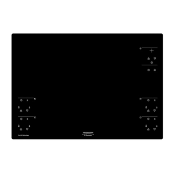
CONTROL SECTION AND BURNERS 3.1 POSITIONS OF THE CONTROLS The figure below illustrates the positions of the controls and the burners. Fig. 1 BR-R (*) RAPID BURNER (FRONT-RIGHT) BR-S/R 1 SEMI-RAPID BURNER (REAR-LEFT) BR-S/R 2 SEMI-RAPID BURNER (REAR-RIGHT) BR-A AUXILIARY BURNER (FRONT-LEFT) BR-R CONTROL TOUCH CONTROL FOR RAPID BURNER (FRONT-RIGHT) BR-S/R 1 CONTROL... -
Page 9: Main On/Off Key
3.2 MAIN ON/OFF KEY The hob is fitted with a main ON/OFF key. The appliance must be switched on before the burners can be ignited. When the appliance is switched on, the corresponding LED lights. The ON/OFF switch can be used to switch off all the burners at the same time, which may be necessary if liquids boil over or in situations in which children may be in danger. -
Page 10: Burner Control Panel
3.3 BURNER CONTROL PANEL Each burner is operated from a specific area of the control panel as indicated in the figure below. Each of the control areas indicates the position of the corresponding burner, the touch control for switching the burner on and off, a LED indicating residual heat, six LEDs indicating the burner setting (level 0 is the lowest setting) and two touch controls for increasing and decreasing the flame. -
Page 11: Timer Control Panel
3.4 TIMER CONTROL PANEL This type of hob also features programmable operation for each burner. The various settings are controlled from the specific zone shown below. The programming function (which switches off the burner at the end of a preset time) can be used for one burner only at a time. -
Page 12: Child Safety Feature
3.5 CHILD SAFETY FEATURE The hob features a child safety system in which the user can disable the controls to prevent inadvertent actioning by children. When the child safety feature has been selected, only the main ON/OFF switch is enabled (see Fig. -
Page 13: Electronic Gas Control System
ELECTRONIC GAS CONTROL SYSTEM 4.1 OVERVIEW OF THE SYSTEM This electronic system is designed to be fitted to Electrolux "Gas on Glass" built-in hobs (70x60 cm) with uncovered burners. Its main characteristics are as follows: Control of four current-production Electrolux burners (uncovered): one rapid, two semi-rapid, one auxiliary. -
Page 14: Operation Of The System
LEDs in the hob control zone. To restore the burners to normal operation after a power failure (LEDs flashing), it is necessary to wait at least 60 seconds and then press buttons simultaneously and then button , after which the burner can be used normally. -
Page 15: Basic Circuit Diagrams
4.3 BASIC CIRCUIT DIAGRAMS BASIC CIRCUIT DIAGRAM: GAS SUPPLY AND CONTROL SYSTEMS Fig. 6 IN GAS GAS INLET MAIN SAFETY VALVE POWERED MODULATION VALVE SPARK PLUG THERMOCOUPLE BR-R RAPID BURNER BR-S/R SEMI-RAPID BURNER BR-A AUXILIARY BURNER TIMER BOARD MAIN TOUCH-CONTROL INTERFACE BOARD TOUCH DX BOARD RH TOUCH-CONTROL INTERFACE BOARD TOUCH SX BOARD... -
Page 16: Ignition Circuit - Basic Diagram
IGNITION CIRCUIT - BASIC DIAGRAM Lighting of the burners is performed by the spark plugs, which are powered by a single spark generator actioned by the power board. Fig. 7 SPARK PLUG THERMOCOUPLE BR-R RAPID BURNER BR-S/R SEMI-RAPID BURNER BR-A AUXILIARY BURNER POWER BOARD POWER BOARD... -
Page 17: System Components
4.4 SYSTEM COMPONENTS The system comprises four circuit boards: one power board and three interface boards. The hob controls are divided among the three general interface boards: General interface and timer board. RH interface board, connected directly to the general interface board. -
Page 18: Sensor Control Interface Circuit Boards
4.4.2 SENSOR CONTROL INTERFACE CIRCUIT BOARDS This hob is provided with a touch sensor control device. To insert the controls in the hob, some sensors interface electronic PCBs are used in place of the normal buttons which control the switches placed in the control unit. - Page 19 MAIN BOARD / TIMER Fig. 11 BR-S/R 1 LED LED FOR REAR LEFT BURNER BR-S/R 2 LED LED FOR REAR RIGHT BURNER BR-A LED LED FOR FRONT LEFT BURNER BR-R LED LED FOR FRONT RIGHT BURNER ON / OFF ON/OFF - REAR RIGHT BR-S/R 2 BURNER BURNER BR-S/R 2 RESIDUAL...
-
Page 20: Powered Flame Modulation Valves
4.4.3 POWERED FLAME MODULATION VALVES The flame control valves comprise two sections: the modulation section and the safety valve section. Fig. 11 ELECTRICAL CONNECTORS (FASTONS) CONNECTOR FOR MODULATION MOTOR VALVE SOLENOID MODULATION MOTOR (STEPPING LINEAR ACTUATOR) GAS INLET COUPLING GAS DELIVERY COUPLING The modulation section SM comprises a pressure regulator which, by means of a stepping linear actuator APP, compresses the regulation spring M1 , thus obtaining one of the six levels of closure of element O1. - Page 21 PRESSURE DIAGRAM WITH 20mbar NATURAL GAS NO. OF STEPS Fig. 14 PRESSURE DIAGRAM WITH 37mbar LIQUID GAS NO. OF STEPS Fig. 15 SOI 04.05 FV 21/57 599 36 62-62...
-
Page 22: Main Safety Solenoid Valve
MODULATION CONTROL MOTOR (STEP-BY-STEP) The modulation control motor of the solenoid valves is a unipolar step-by-step type. Please find below the connection diagram of the motor and the rotation diagram. MOTOR CONNECTION DIAGRAM MOTOR CONNECTOR BLK Black BLK RED RED Red BRW Brown ORG Orange YEL Yellow... -
Page 23: Positions Of The Components Inside The Hob
4.5 POSITIONS OF THE COMPONENTS INSIDE THE HOB The figure below shows the positions of the various components inside the hob. Fig. 18 MAIN SAFETY SOLENOID VALVE LEFT REAR BURNER BR-S/R 1 (SEMI-RAPID) TERMINAL BLOCK FOR POWER SUPPLY SPARK GENERATOR... -
Page 24: Operating The Hob (Extract From Instruction Booklet)
Before using the appliance, remove all packaging material, including advertising labels and protective film, if any. 5.1 TOUCH CONTROL KEYS The hob is operated using special "touch control" sensor keys. To operate the hob, simply touch the appropriate sensor with a fingertip. - Page 25 2. Touch the sensor key for the required burner. All LEDs above the sensor keys will light. Fig. 21 3. Within 3 seconds touch the sensor key turn on the burner. - If the sensor key is touched the burner will turn on automatically at the max.
-
Page 26: Switching Off The Burners
If for any reason the flame should not ignite within this period, the flow of gas to the burner is interrupted and the hob remains in "pause" for about 3 seconds, after which it automatically attempts to ignite the burner for a further period of 6 seconds. -
Page 27: Switching Off All The Burners
The burner can now be used by touching sensor key 5.8 AUTOMATIC HOB SWITCH-OFF If no burner is switched on, even if the hob is activated (the LED above the activation touch key is on), the hob deactivates automatically if within 30 minutes one control is not activated. -
Page 28: Protecting Against Overheating
5.9 PROTECTING AGAINST OVERHEATING If the hob is subjected to intensive use, e.g. if several burners are operated for long periods at maximum flame setting, a temperature sensor checks for possible overheating and, if necessary, automatically reduces the settings of all the burners to minimum level. -
Page 29: Timer
The hob features an electronic timer that enables the user to select a cooking time when the burner is in operation. Also, it is possible to use the timer – when the hob is not in operation – as a minute-minder. - Page 30 The "residual heat" LEDs remain lit even after the hob has been switched off, and until the grille and the burner have cooled down. SOI 04.05 FV...
-
Page 31: Using The Timer With The Burners Switched Off/Minute-Minder Function
To use the timer as a minute-minder, the hob must be switched on. To use this function, proceed as follows: 1. If necessary, switch on the hob by touching the ON / OFF touch key for about three seconds. . 2. Touch sensor key to switch on the timer. -
Page 32: Adapting The Hob To Different Types Of Gas
UNI- CIG standard 7432. 6.2 ADJUSTING THE HOB FOR THE TYPE OF 1. If necessary, switch on the hob by touching the ON / OFF touch key for about three seconds. 2. Touch sensor key to select the auxiliary burner on Fig. -
Page 33: Adjusting The Minimum Setting
6.3 ADJUSTING THE MINIMUM SETTING Fig. 31 Proceed as follows to adjust the minimum setting correctly: 1. Carry out the operations described in "Adjusting the hob for the type of gas", steps 1, 2, 3 and 4. 2. Touch the sensor key to ignite the burner to be adjusted. -
Page 34: Error Codes
To display the error codes, it is sufficient to touch the "clock" sensor and then select the inoperative burner. The error code will be displayed automatically (see Fig. 39 and 40). If the malfunction affects not one single burner but the entire hob, the same code will be displayed for each burner. - Page 35 The table below lists the various error codes with their meanings. ERROR BLOCK ERROR CODE CAUSE COSE DESCRIPTION Normal condition for an operating burner. RROR BURNER Condition of the burner after 3 consecutive LAME FTER ETRY attempts of failed switching on. BURNER EV F Condition of the burner in case of “solenoid...
- Page 36 ERROR BLOCK ERROR CODE CAUSE COSE DESCRIPTION SYSTEM EPROM M Condition of each burner in case a writing error EMORY RITE in EEPROM on the power board is detected. AULT SYSTEM Condition of each burner in case an error on ANGE AULT EEPROM...
-
Page 37: Trouble-Shooting
TROUBLE-SHOOTING 8.1 TROUBLE-SHOOTING USING ERROR CODES Trouble-shooting using error codes identifies the component or the exact section of the circuit in which the fault has occurred. When the control circuit detects a malfunction, the error code is displayed and depending on the code, the operation of the burner is stopped or the appliance is switched off. - Page 38 Condition Control Result Cause Solution Incorrect operation Main electric valve Replace main Check for the of the electric valve. electric valve. faulty. main electric valve. Correct operation of the electric valve. Incorrect operation Burner electric Replace burner Check for the of the electric valve.
-
Page 39: Trouble-Shooting Without Error Codes
Condition Control Result Cause Solution Reset the The connection is Incorrect signal Check for the Error code correct loose. from thermocouple burner connection and to power board. thermocouple (wrong eventually clean connection. thermocoupl the contacts. e back signal) The connection is Thermocouple Replace the correct. -
Page 40: Trouble-Shooting Without Error Codes
The error code 9 Reset the hob Excessive heating Error code 9 Cool down the does not appear as explained in of the hob due to (the hob for at least anymore. the charter an incorrect use of temperature on one hour. - Page 41 8.1.2.1 – SUMMARY TABLE OF ERROR CODES / ACTIONS SUMMARY TABLE ERROR CODE / ACTION ERROR BLOCK ACTION CODE 1 Verify the presence of sparks. 2 Verify the presence of gas. BURNER 3 Verify the sparks. 4 Verify the position of the burner cap and that the flame warms up the thermocouple.
-
Page 42: Troubleshooting Without Error Code
8.2 TROUBLESHOOTING WITHOUT ERROR CODE Some malfunctioning conditions of the hob can appear without any indication of an error code. Please find below some troubleshooting cases without error code. Condition Control Result Cause Solution Interface board- Faulty contacts on Reset the... -
Page 43: Accessibility
ACCESSIBILITY 9.1 REMOVAL OF TOP FROM THE CABINET To remove the top from the cabinet, move the top from the lower part. Fig. 41 Fig. 42 9.2 REMOVAL OF GAS SUPPLY CONNECTION After closing the gas supply, switched off the power supply, remove the top and positioned the top so as to access the gas connection easily (Ex.: by using wood trims to keep the top raised) detach the gas delivery pipe (see Fig. -
Page 44: Removal Of Upper Top
9.3 REMOVAL OF UPPER TOP To remove the glass upper top after extracting the top from the cabinet: - Remove the grids and the flame spreader crowns of the burners (see Pic. 43). Fig. 44 1 - GRID 2 - FLAME SPREADER CROWN - Remove the 6 screws which fit the upper glass (see Fig. - Page 45 Fig. 46 1 - FIXING SCREWS RAPID BURNER 2 - FIXING SCREWS SEMI-RAPID BURNER (REAR LEFT) 3 - FIXING SCREWS SEMI-RAPID BURNER (REAR RIGHT) 4 - FIXING SCREWS AUXILIARY BURNER Fig. 47 1 - GLASS UPPER TOP 2 - TOP EXTERNAL CASING 3 –...
-
Page 46: Access To Component Zone
9.4 ACCESS TO COMPONENT ZONE After removing the upper top the various internal components can be accessed (see Fig. 48) . Fig. 48 1 - LEFT REAR BURNER (SEMI-RAPID) 2 - INTERFERENCE SUPPRESSOR 3 - JUNCTION BOX 4 - IGNITER 5 - RIGHT REAR BURNER (SEMI-RAPID) 6 - MAIN INTERFACE BOARD 7 - POWER BOARD... -
Page 47: Dismounting The Burner Control Electrica Valves
- Detach the power supply connector. NOTE: The upper screws can be accessed after dismounting the left interface board and the power board. The lower screws can be accessed from the left lower side part of the hob (see Fig. 50). Fig. 49... -
Page 48: Dismounting The Main Safety Electric Valve
9.4.2 DISMOUNTING THE MAIN SAFETY ELECTRIC VALVE To dismount the main safety electric valve after removing the gas input connection: Remove the electric valve connection nut – feed pipe (see Fig. 52). Remove the two fixing screws of the electric valve placed at the top bottom (see Fig. 51). Detach the power supply cables. -
Page 49: Replacement Of Interface Boards
9.4.3 REPLACEMENT OF INTERFACE BOARDS To replace the interface boards: Release the board from the fixing plastic clips (see Fig. 54). Detach the connector. Fig. 53 1 - INTERFACE BOARD 2 - FIXING CLIPS 3 - SENSOR CONTROL ZONES Fig. 54 1 - INTERFACE BOARD 2 - FIXING CLIPS SOI 04.05 FV... -
Page 50: Replacement Of Power Board
9.4.4 REPLACEMENT OF POWER BOARD To replace the power board: Raise the two metallic tabs by using a screwdriver (see Fig. 55 and 56). Detach the connectors and the connection terminals making a sign for the position to facilitate the remounting. -
Page 51: Replacement Of Burners
To remove the power board from the plastic support release the board from its fixing hooks (see Fig. 56). Fig. 57 1 - SCREWDRIVER 2 - FIXING HOOK 3 - POWER BOARD 4 - PLASTIC SUPPORT 9.4.5 – REPLACEMENT OF BURNERS To replace a burner: Dismount the spark plug and the thermocouple. -
Page 52: Replacement Of Thermocouples
Fig. 59 1 - TOP BOTTOM 2 - BURNER FIXING SCREWS 9.4.6 REPLACEMENT OF THERMOCOUPLES To replace the thermocouples: Release the thermocouple removing the fixing spring placed in the lower side part of the burner. Detach the thermocouple terminal placed on the power board. (see Fig. - Page 53 Fig. 61 1 - THERMOCOUPLE CONNECTION TC1 (BLACK - LEFT FRONT BURNER) 2 - THERMOCOUPLE CONNECTION TC2 (BLUE - RIGHT FRONT BURNER) 3 - THERMOCOUPLE CONNECTION TC3 (RED - RIGHT REAR BURNER) 4 - THERMOCOUPLE CONNECTION TC4 (WHITE - LEFT REAR BURNER) 5 - POWER BOARD 6 - INTERFACE BOARD VIEW OF SPARK PLUG AND THERMOCOUPLE FIXING...
-
Page 54: Replacement Of Ignition Spark Plugs
9.4.7 REPLACEMENT OF IGNITION SPARK PLUGS To replace the spark plugs: Detach the connection terminal relative to the spark plug. Detach the spark plug removing the fixing spring placed in the lower side part of the burner. Fig. 63 1 - IGNITER. 2 - SPARK PLUG CONNECTION TERMINAL. -
Page 55: Electric Diagrams
10. ELECTRIC DIAGRAMS 10.1 BASIC ELECTRIC DIAGRAM SOI 04.05 FV 55/57 599 36 62-62... -
Page 56: Wiring Diagram
10.2 WIRING DIAGRAM SOI 04.05 FV 56/57 599 36 62-62... -
Page 57: Key To Diagram
10.3 KEY TO DIAGRAM DESCRIPTION Igniter Interference suppressor Earth Power board Timer board Sensor control board Main electric valve Burner electric valve Burner Thermocouple SOI 04.05 FV 57/57 599 36 62-62...
Need help?
Do you have a question about the Hob and is the answer not in the manual?
Questions and answers