
Subscribe to Our Youtube Channel
Related Manuals for Inline IN3504


Summary of Contents for Inline IN3504
- Page 1 Operation Manual IN3504: 4 –In 1-Out RGBS Switcher IN3506: 6 –In 1-Out RGBS Switcher ®...
-
Page 2: Installation And Safety Instructions
For continued protection against fire hazard, replace only with same type and rating of fuse. For IN2001 / IN3234 / IN3236 / IN3502 / IN3504 / IN3506 / IN3562 / IN3564 / IN3566 / IN3572 / IN3574 / IN3576: Caution: Double pole / neutral fusing. -
Page 3: Installations Und Sicherheitshinweise
Für dauernden Schutz gegen Feuergefahr darf die Sicherung nur gegen eine andere gleichen Typs und gleicher Nennleistung ausgewechselt werden. Für IN2001 / IN3234 / IN3236 / IN3502 / IN3504 / IN3506 / IN3562 / IN3564 / IN3566 / IN3572 / IN3574 / IN3576: Achtung: Allpolige Absicherung Für alle Geräte mit eingebauter Lithium Batterie:... -
Page 4: Fcc Compliance
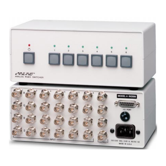
CE COMPLIANCE All products exported to Europe by Inline, Inc. after January 1, 1997 have been tested and found to comply with EU Council Directive 89/336/EEC. These devices conform to the following standards: EN50081-1 (1991), EN55022 (1987) EN50082-1 (1992 and 1994), EN60950-92... - Page 5 The IN3506 is a 6-Input 1 Output RGBS switcher. The IN3504 / IN3506 switchers feature a set of four BNCs for each input and output connection and can switch four discrete signal components for each input. The IN3504 / IN3506 are compatible with analog computer video signals in any of the following formats: RGBS, RGsB, RsGsBs, and composite monochrome with sync.
-
Page 6: Installation
Input Selection The IN3504 / IN3506 switchers provide four or six front panel buttons which may be used to select the desired input channel. Any time the unit is powered up, Input 1 is automatically selected. In order to select a different input, press the corresponding input button and the appropriate green LED will light to indicate the current active channel. - Page 7 Application Diagram IN3506 VGA Computer G A I N G A I N HORIZONTAL R E D HORIZONTAL R E D POSITION POSITION G R E E N G R E E N B L U E B L U E BLUE BLUE CONTROL...
-
Page 8: Remote Control Operation
REMOTE CONTROL OPERATION The IN3504 / IN3506 RGBS switchers have a REMOTE CONTROL port which allows these units to be remotely controlled. Channels can be selected through the remote port by providing contact closures between the appropriate pins. The port also includes a +5V power supply and tally outputs. Several contact closure type control devices are available including: IN3590 - An optional hard wired remote designed to work with IN3500 Series switchers. -
Page 9: Internal Fuses
INTERNAL FUSES The IN3504 / IN3506 switchers contain two internal fuses. If power is applied to the unit and the front panel power LED will not light after the POWER switch has been activated, these fuses may be blown. -
Page 10: Troubleshooting
Solution: The control system may be closing two contacts at the same time. Check the wiring on the control cable and the control system programming. IN3504/IN3506 OPERATION MANUAL - REV. 3.0 11/27/99 ©1995-1999 - INLINE, INC. -
Page 11: Warranty
The information in this manual has been carefully checked and is believed to be accurate. However, Inline, Inc. assumes no responsibility for any inaccuracies that may be contained in this manual. In no event will Inline, Inc. be liable for direct, indirect, special, incidental, or consequential damages resulting from any defect or omission in this manual, even if advised of the possibility of such damages.
Need help?
Do you have a question about the IN3504 and is the answer not in the manual?
Questions and answers