
Related Manuals for Inline IN3552R


Summary of Contents for Inline IN3552R
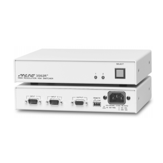
- Page 1 Operation Manual 2-Input, 1-Output Switcher Series: IN3552R - RGBHV Switcher IN3562R - VGA Switcher...
- Page 2 Installation and Safety Instructions For Models without a Power Switch: The socket outlet shall be installed near the equipment and shall be accessible. For Models with 110 / 220V Power Selector: Caution: Before applying power to this unit, the voltage selector must be set to the appropriate setting to match local A/C line voltage.
- Page 3 Installations und Sicherheitshinweise Für Geräte ohne Netzschalter: Die Netzsteckdose soll in de Nähe des Gerätes installiert und frei zugänglich sein. Für Geräte mit 110 / 220V Spannungswähler: Achtung: Bevor Sie dem Gerät Spann ung zuführen, muß der Spannungswähler entsprechend der Spannung des lokalen Wechselspannungsnetzes eingestellt werden.
-
Page 4: Fcc Compliance
CE COMPLIANCE All products exported to Europe by Inline, Inc. after January 1, 1997 have been tested and found to comply with EU Council Directive 89/336/EEC. These devices conform to the following standards: EN50081-1 (1991), EN55022 (1987) EN50082-1 (1992 and 1994), EN60950-92... - Page 5 IN3552R RGBHV Analog Video Switcher - is a two input, one output switcher featuring a set of five BNCs for each input and output connection. The unit can switch five discrete signal components for each input and is compatible with analog computer video signals in any of the following formats: RGBHV, RGBS, RGsB, RsGsBs, and composite monochrome with sync.
-
Page 6: Installation
1. Connect both sources to the IN3552R / IN3562R input connectors. IN3552R: An interface may be required for each computer video signal source in order to split off a signal for each local monitor, bring all signals into the RGBHV format, and amplify the signal to compensate for long input/output cable runs. - Page 7 Application Diagram - IN3562R Local Monitor IN3262 / IN3262D PC with Data Projector / VGA Out Data Monitor 3262 ® HIGH RESOLUTION VGA DISTRIBUTION AMPLIFIER IN8000 Series VGA Cables INPUT 1 INPUT 2 OUTPUT REMOTE IN3562R STAT 120/230VAC; 0.04A; 60/50 HZ AC SETTING: 120 VAC 230 VAC...
-
Page 8: Remote Control Operation
OPERATION Input Selection The IN3552R / IN3562R two input switchers provide a front panel button which may be used to select the desired input channel. Each time the SELECT button is pressed the unit toggles back and forth between Input 1 and Input 2 and the appropriate front panel LED indicator lights to show the current channel selection. - Page 9 Contact Closure Devices Any device capable of providing a latching contact closure may be used to control the IN3552R / IN3562R. Several contact closure type control devices are available: IN6901 / IN6902 RS-232 to Contact Closure Converters - allow IN3500 Series switchers and other INLINE devices with contact closure control ports to be controlled by RS-232 sources such as control systems and computer serial ports.
-
Page 10: Internal Fuses
2. Loosen and remove the four case screws on the sides of the unit. 3. Lift off the top half of the IN3552R / IN3562R case. Capacitor C1 may store an electrical charge even when the unit is powered down. Take care not to touch this component. -
Page 11: Specifications
4 lbs. / 2 Kg Regulatory Approval UL 1950, 3 Ed.; CE: EN60950-92; Safety CAN/CSA-22.2 No. 950 3 FCC class A; CE: EN50081-1, EMI / ESD EN55022, EN50082-1 © 1999 - INLINE, INC. IN3552R / IN3562R OPERATION MANUAL - REV. 1.0 11/27/99... -
Page 12: Troubleshooting
When controlling the switcher through the REMOTE CONTROL port, Input 2 can be selected for an instant, but then the unit quickly switches back to Input 1. Solution: The control system may be providing a momentary contact closure. The IN3552R/IN3562R require a latching closure to select Input channel 2. -
Page 13: Warranty
The information in this manual has been carefully checked and is believed to be accurate. However, Inline, Inc. assumes no responsibility for any inaccuracies that may be contained in this manual. In no event will Inline, Inc. be liable for direct, indirect, special, incidental, or consequential damages resulting from any defect or omission in this manual, even if advised of the possibility of such damages.
Need help?
Do you have a question about the IN3552R and is the answer not in the manual?
Questions and answers