Tennant 7400 Gas Operator's Manual
Rider scrubber
Hide thumbs
Also See for 7400 Gas:
- Operator's manual (86 pages) ,
- Operator's manual (88 pages) ,
- Service manual (322 pages)
Table of Contents

Related Manuals for Tennant 7400 Gas


Summary of Contents for Tennant 7400 Gas
- Page 1 7400 (Gas/LPG) (007000- - (GM Engine) Rider Scrubber Operator Manual The Safe Scrubbing Alternative ES Extended Scrub System 330970 North America / International Rev. 04 (3-2007) *330970* www.tennantco.com Home Find... Go To..
- Page 2 Engine exhaust from this product contains chemicals known to the State of California to cause cancer, birth defects, or other reproductive harm. FaST- -PAK is a US registered and unregistered trademark of Tennant Company. Specifications and parts are subject to change without notice.
-
Page 3: Table Of Contents
CONTENTS CONTENTS Page Page SAFETY PRECAUTIONS ....POST-OPERATION CHECKLIST ..OPERATION ......OPERATION ON INCLINES . - Page 4 CONTENTS Page SQUEEGEE BLADES ....REAR SQUEEGEE ....REPLACING OR ROTATING REAR SQUEEGEE BLADES .
-
Page 5: Safety Precautions
SAFETY PRECAUTIONS SAFETY PRECAUTIONS The following precautions are used throughout FOR SAFETY: this manual as indicated in their description: 1. Do not operate machine: WARNING: To warn of hazards or - - Unless trained and authorized. unsafe practices that could result in - - Unless operator manual is read and understood. - Page 6 Keep area well ventilated. - - Use cardboard to locate leaking hydraulic fluid under pressure. - - Use Tennant supplied or approved replacement parts. 7. When loading/unloading machine onto/off truck or trailer: - - Turn off machine.
- Page 7 SAFETY PRECAUTIONS The following safety labels are mounted on the machine in the locations indicated. If these or any labels become damaged or illegible, install a new label in its place. FOR SAFETY LABEL - - LOCATED ON THE SIDE OF THE OPERATOR COMPARTMENT. EMISSIONS LABEL - - LOCATED ON THE SIDE OF THE OPERATOR COMPARTMENT.
- Page 8 SAFETY PRECAUTIONS FAN AND BELT LABEL - - LOCATED ON THE STRONG VACUUM LABEL - - LOCATED ON ENGINE COMPARTMENT LINTEL. THE VACUUM FAN HOUSING. HOT SURFACE LABEL - - LOCATED ON THE SIDE OF THE BUMPER. 10783 FLAMMABLE MATERIALS LABEL - - LOCATED NEXT TO THE SOLUTION TANK COVERS AND ON THE DETERGENT TANK.
-
Page 9: Operation
Tennant representative. - Order parts and supplies directly from your authorized Tennant representative. Use the parts manual provided when ordering parts. - After the first 50 hours of operation, follow the recommended procedures stated in the MAINTENANCE CHART. -
Page 10: Machine Components
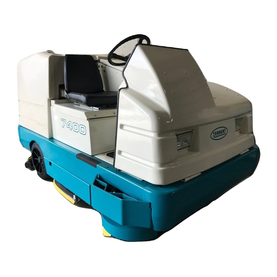
OPERATION MACHINE COMPONENTS 10783 A. Instrument panel B. Steering wheel C. Operator seat D. Engine cover E. Machine front cover F. Solution tank covers G. Solution tanks H. Recovery tank covers Recovery Tank J. Rear squeegee K. Side Squeegee L. Scrub brush access door M. -
Page 11: Symbol Definitions
OPERATION SYMBOL DEFINITIONS These symbols identify controls, displays, and features on the machine: Charging system Steering tilt Engine oil pressure Horn High engine temperature Ignition switch Maintenance mode Circuit breaker 1 Recovery tank full Circuit breaker 2 Fuel Circuit breaker 3 Diagnostics Circuit breaker 4 Hourmeter... -
Page 12: Controls And Instruments
OPERATION CONTROLS AND INSTRUMENTS 10654 A. Directional pedal B. Brake pedal C. Parking brake pedal D. Charging system light E. Engine oil pressure light F. High engine temperature light G. Maintenance mode light H. Recovery tank full light Fuel level low light J. -
Page 13: Operation Of Controls
OPERATION OPERATION OF CONTROLS DIRECTIONAL PEDAL The directional pedal controls direction of travel and the propelling speed of the machine. You change the speed of the machine with the pressure of your foot; the harder you press the faster the machine travels. Forward: Press the top of the directional pedal with the toe of your foot. -
Page 14: Brake Pedal
OPERATION BRAKE PEDAL The brake pedal stops the machine. Stop: Take your foot off the directional pedal and let it return to the neutral position. Step on the brake pedal. PARKING BRAKE PEDAL The parking brake pedal sets and releases the rear wheel brakes. -
Page 15: Engine Oil Pressure Light
OPERATION ENGINE OIL PRESSURE LIGHT The engine oil pressure light comes on when the engine oil pressure falls below 40 kPa (5 psi). Stop operating the machine. Locate the problem and have it corrected. 10643 HIGH ENGINE TEMPERATURE LIGHT The high engine temperature light comes on when the temperature of the engine coolant is more than 107_ C (225_ F). -
Page 16: Recovery Tank Full Light
OPERATION RECOVERY TANK FULL LIGHT The recovery tank full light starts blinking when the recovery tank is full. The light will blink for one minute and then stay on. Then the scrubbing operations will shut off. FUEL LEVEL LOW LIGHT 10886 The fuel level low light comes on when the gasoline or LPG fuel tank is almost empty. -
Page 17: Fuel Level Gauge
OPERATION FUEL LEVEL GAUGE The fuel level gauge indicates how much fuel is in the fuel tank with a segmented LED light. Gasoline powered machine: When the tank is full, all ten of the LED segments are lit. As the fuel tank empties, the LED segments shut off. -
Page 18: Es Switch (Option)
OPERATION ES SWITCH (OPTION) The ES switch turns on and off the extended scrub system. When the machine is started, the ES switch will default to the last setting used. On: Press the ES switch. The indicator light above the switch will come on. Off: Press the ES switch. -
Page 19: Scrub Switch
OPERATION SCRUB SWITCH The scrub switch controls the scrubbing operations. The scrub switch also sets the scrub brush pressure. The scrubbing operations include the following. The scrub head lowers and the brushes turn on. The rear squeegee will lower and the vacuum fan will start. -
Page 20: Engine Speed Switch
OPERATION ENGINE SPEED SWITCH The engine speed switch controls the engine governed speed. The two indicator lights above the switch show the engine speed; idle or fast. Idle: The engine will automatically start in idle speed. To return the engine to idle from the (Fast) engine speed, press the engine speed switch until the left indicator light comes on. -
Page 21: Horn Button
OPERATION HORN BUTTON The horn button operates the horn. Sound: Press the button. IGNITION SWITCH The ignition switch starts and stops the engine with a key. The operating lights will automatically turn on when the machine is started. FOR SAFETY: When starting machine, keep foot on brake and directional pedal in neutral. -
Page 22: Check Engine Light
The check engine light comes on if the engine control system detects a fault during machine operation. If the check engine light comes on while operating the machine, contact a TENNANT service representative. CIRCUIT BREAKERS The circuit breakers are resetable electrical circuit protection devices. -
Page 23: Fuses
OPERATION FUSES The fuses are one-time protection devices designed to stop the flow of current in the event of a circuit overload. NOTE: Always replace the fuse with a fuse of the same amperage. The main harness fuse is located near the relays under the front hood. -
Page 24: Solution Flow Switch (Without Fast)
OPERATION SOLUTION FLOW SWITCH (WITHOUT FaST) The solution flow switch controls the flow of solution to the floor. The solution flow switch is only on machines without the FaST system. Start (1): Place the solution flow switch in the middle position. Use this flow rate for smooth floors and light dirt. -
Page 25: Solution Tank Drain Hose
OPERATION SOLUTION TANK DRAIN HOSE The solution tank drain hose is used to drain the solution tank. Drain the solution tank by removing the drain hose cap from the tank access cap. Pull out the solution tank hose and remove the drain hose end cap. -
Page 26: Operator Seat
OPERATION OPERATOR SEAT The operator seat is a fixed back style with a forward-backward position adjustment. Adjust: Pull the lever, slide the seat backward or forward to the desired position and release the lever. Lift: Pull up on the seat mounting plate until the seat mount locks up. -
Page 27: How The Machine Works
OPERATION HOW THE MACHINE WORKS The steering wheel controls the direction of machine travel. The directional pedal controls the speed and forward/reverse direction. The brake pedal slows and stops the machine. Water and detergent, from the solution tank, flow to the floor through a solution valve to the scrub brushes. -
Page 28: Fast Scrubbing System
Conventional cleaning detergents/ restorers may cause failure to the FaST solution system. NOTE: Storage or transporting machines equipped with FaST in freezing temperatures requires special procedures. Check with a TENNANT representative for advice. 7400 (GM) 330970 (3- -07) Home Find... Go To.. -
Page 29: Pre-Operation Checklist
OPERATION PRE-OPERATION CHECKLIST - Check under the machine for leaks (fuel, oil, coolant, scrubbing solution). - Check the engine air filter indicator. - Check the engine oil level. - Check the fuel level. - Check the brakes and steering for proper operation. -
Page 30: Installing Fast Pak Agent
OPERATION INSTALLING FaST PAK AGENT NOTE: Machine must be equipped with FaST before the FaST PAK agent can be installed. 1. Remove the perforated knock--outs from the FaST PAK Floor Cleaning Concentrate carton. Do not remove the bag from the carton. -
Page 31: Home Find... Go To
OPERATION Connect the supply hose to the FaST PAK bag. NOTE: If any dried concentrate is visible on the supply hose connector or the on the FaST PAK connector, soak and clean with warm water. 5. Place the FaST PAK carton in the carton holder under the seat mounting plate on the machine. -
Page 32: Changing An Lpg Fuel Tank
OPERATION CHANGING AN LPG FUEL TANK 1. Park the machine in a designated safe area. 2. Open the machine front cover. 3. Close the tank service valve on the LPG tank. 4. Operate the engine until it stops from lack of fuel, turn the ignition switch off, then set the machine parking brake. -
Page 33: Starting The Machine
OPERATION 9. Connect the LPG fuel line to the tank service coupling. Make sure the service coupling is clean and free of damage. Also make sure it matches the machine service coupling. 07813 10. Open the tank service valve slowly and check for leaks. -
Page 34: Home Find... Go To
OPERATION 3. Turn the ignition switch key clockwise until the engine starts. NOTE: Do not operate the starter motor for more than 10 seconds at a time or after the engine has started. Allow the starter to cool between starting attempts or damage to the starter motor may occur. -
Page 35: Scrubbing And Brush Information
OPERATION SCRUBBING AND BRUSH INFORMATION Pick up oversized debris before scrubbing. Pick up pieces of wire, string, twine, etc., which could become wrapped around the scrubbing brushes. Plan the scrubbing in advance. Try to arrange long runs with minimum stopping and starting. Do an entire floor or section at one time. -
Page 36: Filling The Tanks
OPERATION Polypropylene side scrub brush -- A general-purpose brush with stiff bristles for aggressive action on slightly compacted soilage. Works well on concrete, wood, and tile surfaces. Nylon side scrub brush -- Recommended for scrubbing coated floors. Cleans without scuffing. Super abrasive bristle side scrub brush -- Nylon fiber impregnated with abrasive grit to remove stains and soilage. -
Page 37: Home Find... Go To
For specific recommendations, contact your Tennant representative. WARNING: Flammable materials can cause an explosion or fire. Do not use flammable materials in tank(s). -
Page 38: Scrubbing
OPERATION ES mode with auto-fill (option): Connect the hose from the water source to the auto-fill connection on the machine. Turn the ignition key to the on position and turn on the water source. The auto-fill will automatically fill the tanks to the proper level for ES operation and automatically shut-off. -
Page 39: Home Find... Go To
OPERATION 4. CONVENTIONAL SCRUBBING: Adjust the solution flow to the floor as needed. See the SOLUTION SWITCH (WITHOUT FaST) section of the manual. 5. Press the scrub switch to start the scrubbing operations. WARNING: Flammable materials or reactive metals can cause an explosion or fire. -
Page 40: Home Find... Go To
OPERATION NOTE: If you do not want to use the ES system, press the ES switch so the indicator above the switch is off. 10898 Press and hold the detergent switch until both indicator lights are off. Turn off the detergent pump only if detergent has been added to the solution tank. -
Page 41: Double Scrubbing
OPERATION DOUBLE SCRUBBING Double scrubbing is a method for removing heavy soil accumulations. This is done by making two passes over the area, to be cleaned, with the machine. Double scrubbing can be performed using the FaST SCRUBBING SYSTEM or CONVENTIONAL SCRUBBING methods. -
Page 42: Draining And Cleaning The Tanks
OPERATION DRAINING AND CLEANING THE TANKS When you are finished scrubbing or the recovery tank full light comes on, the recovery tank should be drained and cleaned. The solution tank then can be filled again for additional scrubbing. If you used the machine in ES mode, the solution tank should also be drained and cleaned when you are finished scrubbing. -
Page 43: Home Find... Go To
OPERATION 5. Unscrew the drain hose cap from the access cap of the recovery tank drain. 6. Pull out and place the drain hoses next to the floor drain. Remove the drain end cap from the hose. Stand back, the solution rushes out of the drain hoses. -
Page 44: Home Find... Go To
OPERATION 10. ES mode: Clean the ES filter. If the filter can’t be rinsed off through the right recovery tank fill opening, the filter can be removed from the recovery tank by disconnecting the ES pump wire and solution hose, and unscrewing the ES pump cap from the recovery tank. -
Page 45: Stop The Machine
OPERATION STOP THE MACHINE 1. Stop scrubbing and drive the machine forward until the vacuum fan shuts off. 2. Take your foot off the directional pedal. Step on the brake pedal. 3. Select the (Idle) position with the engine speed switch. 10900 4. -
Page 46: Home Find... Go To
OPERATION 5. Turn the ignition switch key counter-clockwise to stop the engine. Remove the switch key. NOTE: To protect the engine’s emission components on LPG powered machines, the engine will continue to operate for a few seconds after the ignition switch is turned off. FOR SAFETY: Before leaving or servicing machine;... -
Page 47: Post-Operation Checklist
OPERATION POST-OPERATION CHECKLIST - Check the brush adjustment. See TO CHECKING AND ADJUSTING SCRUB BRUSH PATTERN in MAINTENANCE. - Check for wire, string, or twine wrapped around the scrub brushes. - Check the squeegees for wear or damage. - Drain and clean the recovery tank. - ES mode: Drain and clean the solution tank and clean the solution outlet filter. -
Page 48: Options
OPERATION OPTIONS VACUUM WAND The vacuum wand uses the machine’s vacuum system. The vacuum hose and wand allows pick-up of spills that are out of reach of the machine. WARNING: Flammable materials or reactive metals can cause an explosion or fire. Do not pickup. 1. - Page 49 OPERATION 4. Remove the squeegee suction hose from the rear squeegee and connect the vacuum hose. 5. Put together the wand and the wand hose. 6. Start the engine. 7. Select the (Fast) engine speed with the engine speed switch. 10900 8.
- Page 50 OPERATION 9. Vacuum the floor. 06599 10. Shut the engine off. 11. Remove the vacuum hose from the squeegee suction hose and connect the squeegee suction hose to the rear squeegee. 12. Put the vacuum wand and hose in the mounting clips.
-
Page 51: Machine Troubleshooting
Solution flow switch turned off. Turn solution flow switch on. Poor scrubbing performance. Debris caught on scrub brushes. Remove debris. Improper detergent or brushes Check with Tennant representative used. for advice. Worn scrub brushes. Replace scrub brushes. ES system does not fill solution Clogged solution pump or lines. - Page 52 To prime, operate the FaST solu- tion system for 5 to 10 minutes. Clogged flow control orifice/screen Remove and clean orifice/screen Faulty pump or air compressor Contact TENNANT representative Clogged filter screen Drain solution tank, remove and clean filter screen...
- Page 53 OPERATION 7400 (GM) 330970 (3- -05) Home Find... Go To..
-
Page 54: Maintenance
MAINTENANCE MAINTENANCE 10703 MAINTENANCE CHART NOTE: Check procedures indicted (H) after the first 50-hours of operation. No. of Lubricant/ Service Fluid Interval Description Procedure Points Check indicator Daily Engine Empty dust cap Check oil level Check coolant level in reservoir Check for damage and wear Rear Squeegee Check deflection... - Page 55 . . . Water and permanent-type ethylene glycol anti-freeze, --34_ C (--30_ F) . . . Special lubricant, Lubriplate EMB grease (TENNANT part no. 01433--1) ..Distilled water NOTE: More frequent intervals may be required in extremely dusty conditions.
-
Page 56: Lubrication
REAR WHEEL BEARINGS Inspect the rear wheel bearings for seal damage, and repack and adjust every 400 hours of operation. Use Lubriplate EMB grease (Tennant part number 01433--1). FRONT WHEEL SUPPORT BEARING The front wheel support pivots the front wheel. -
Page 57: Scrub Brush Idler
Each scrub brush idler has one grease fitting. The scrub brush idlers must be lubricated every 100 hours of operation. Use Lubriplate EMB grease (Tennant part no. 01433--1). HYDRAULICS HYDRAULIC FLUID RESERVOIR The reservoir is located in front left corner of the machine. -
Page 58: Hydraulic Fluid
The quality and condition of the hydraulic fluid play a very important role in how well the machine operates. Tennant hydraulic fluid is specially selected to meet the needs of Tennant machines. Tennant hydraulic fluids provide a longer life for the hydraulic components. There are two fluids available for different temperature ranges: Tennant part no. -
Page 59: Engine
MAINTENANCE ENGINE COOLING SYSTEM Check the coolant level in the reservoir daily. The coolant level must be between the two indicator marks when the engine is cold. Check the radiator coolant level every 100 hours of operation. Use a clean water mixed with a permanent-type, ethylene glycol antifreeze to a --34_ C (--30_ F) rating. - Page 60 MAINTENANCE The coolant system must be completely filled with coolant to keep the engine from overheating. When filling the radiator with coolant, use the drain cocks to ensure that all the air is out of the system. Gasoline Only LP Only LP/Gasoline 7400 (GM) 330970 (3- -07) Home...
-
Page 61: Air Filter Indicator
MAINTENANCE Check the radiator hoses and clamps every 200 hours of operation. Tighten the clamps if they are loose. Replace the hoses and clamps if the hoses are cracked, hardened, or swollen. Check the radiator core exterior and hydraulic cooler fins for debris every 100 hours of operation. -
Page 62: Air Filter
MAINTENANCE AIR FILTER For machines serial number 008999 and below. The engine air filter housing has a dust cap and a dry cartridge-type air filter element. Empty the dust cap daily. The air filter must be replaced whenever the filter element is damaged. Replace the air filter element every 400 hours or when the air filter indicator shows restriction in the air intake system. -
Page 63: Fuel Filter (Lpg)
MAINTENANCE FUEL FILTER (LPG) The fuel filter traps fuel contaminants. The fuel filter element is located inside the fuel lockoff valve on the LPG convertor going into the electronic fuel injection system. FOR SAFETY: When servicing machine, keep flames and sparks away from fuel system service area. -
Page 64: Battery
MAINTENANCE BATTERY The battery for the machine is a low maintenance battery. Do not add water to the battery, or remove the battery vent plugs. The battery is located under the operator seat. After the first 50 hours of operation, and every 800 hours after that, clean and tighten the battery connections. -
Page 65: Scrub Brushes
MAINTENANCE SCRUB BRUSHES Two cylindrical scrub brushes span the width of the scrub head, sweeping debris into the debris tray while scrubbing the floor. The scrub brushes should be checked daily for tangled wire or string, wear, and damage. The scrub brushes can be rotated front-to-rear, and end-for-end to increase brush life.The brushes should be replaced if large portions of the brush bristles are missing or if the remaining... -
Page 66: Replacing Or Rotating The Scrub Brushes
MAINTENANCE REPLACING OR ROTATING THE SCRUB BRUSHES 1. Set the machine parking brake. 2. Turn off the solution flow switch. 3. Stop the engine. 4. Turn the ignition to accessories, do not start the engine. Lower the scrub head with the scrub switch. -
Page 67: Checking And Adjusting Scrub Brush Pattern
MAINTENANCE 10. Pull out the front brush and then the rear brush. 11. Line up the drive end of the new or rotated brushes with the brush drive plugs. The cylindrical scrub brushes must be installed with the V-patterns on the brushes pointing towards each other. - Page 68 MAINTENANCE 4. Lower the scrub head for 15 to 20 seconds while keeping the scrub head in one spot in the chalked area. NOTE: If chalk or other material is not available, allow the brushes to spin on the floor for two minutes.
- Page 69 MAINTENANCE The brush patterns should be the same width. If one is narrower then the other, the scrub head needs to be leveled from front to rear. 10653 A. Lengthen or shorten the leveling rods on both sides of the scrub head. Lengthening the rods will increase the rear brush pattern width.
-
Page 70: Solution System
MAINTENANCE SOLUTION SYSTEM RECOVERY TANK The recovery tank stores recovered solution. The recovery tank should be drained and cleaned daily, or when the recovery tank full light comes ES option: The ES filter should be cleaned daily. The ES filter can be rinsed while in the recovery tank through the right tank fill opening, or by removing the ES pump from the recovery tank. -
Page 71: Fast System
MAINTENANCE FaST SYSTEM FaST SUPPLY HOSE CONNECTOR The FaST supply hose connector is located on the side of the the FaST PAK holder. Soak the connector in warm water if detergent buildup is visible. When a FaST PAK carton is not installed, store the supply hose connector on the storing plug to prevent the hose from clogging. -
Page 72: Fast Spray Tube
MAINTENANCE FaST SPRAY TUBE The FaST spray tube is located on the front of the scrub brush housing. Debris from the spinning scrub brushes can collect on the spray tube. Rinse and clean the tube with a strong blast of warm water after every 50 hours of machine operation. - Page 73 MAINTENANCE 3. Look at the deflection over the full length of the squeegee blade. The correct amount of 5 mm 15 to deflection for the rear squeegee blade is (0.13 to 20 mm 15 to 20 mm (0.50 to 0.75 in). The front 0.25 in) (0.50 to slotted squeegee blade should contact the...
-
Page 74: Leveling The Rear Squeegee
MAINTENANCE LEVELING THE REAR SQUEEGEE Leveling of the squeegee assures even contact over the length of the squeegee blade with the surface being scrubbed. Make sure this adjustment is done on an even, level floor. 1. Lower the squeegee and drive the machine forward. -
Page 75: Squeegee Blades
MAINTENANCE SQUEEGEE BLADES REAR SQUEEGEE Check the squeegee blades for damage and wear daily. Rotate or replace either of the squeegee blades if the leading edge is torn or worn half-way through the thickness of the blade. The rear squeegee has two squeegee blades. Each blade has four wiping edges. -
Page 76: Side Squeegees
MAINTENANCE 4. Replace or rotate the squeegee blade to allow a new edge to face the front of the machine. 5. Place the squeegee blade over the pins of the squeegee frame. 6. Position the retaining band over the squeegee blade. Latch the retaining band clamp. -
Page 77: Skirts And Seals
MAINTENANCE SKIRTS AND SEALS SCRUB HEAD SKIRTS A skirt is mounted on each side of the scrub head. Check the skirts for wear or damage every 100 hours of operation. COVER SEALS Check the solution and recovery tank cover seals for wear or damage every 100 hours of operation 7400 (GM) 330970 (12- -03) Home... -
Page 78: Brakes And Tires
MAINTENANCE BRAKES AND TIRES SERVICE BRAKES The mechanical service brakes are located on the rear wheels. The brakes are operated by the foot brake pedal and connecting cables. Check the brake adjustment every 200 hours of operation. PARKING BRAKE The parking brake is set with the parking brake pedal that activates the service brakes. -
Page 79: Pushing, Towing, And Transporting The Machine
MAINTENANCE PUSHING, TOWING, AND TRANSPORTING THE MACHINE PUSHING OR TOWING THE MACHINE If the machine becomes disabled, it can be pushed from the front or rear, but towed only from the rear. The propelling pump has a bypass valve to prevent damage to the hydraulic system when the machine is being pushed or towed. -
Page 80: Transporting The Machine
MAINTENANCE TRANSPORTING THE MACHINE 1. Position the rear of the machine at the loading edge of the truck or trailer. 2. If the loading surface is not horizontal or is higher than 380 mm (15 in) from the ground, use a winch to load machine. If the loading surface is horizontal AND is 380 mm (15 in) or less from the ground, the machine may be driven onto the truck or... - Page 81 MAINTENANCE 5. Position the machine onto the truck or trailer as far as possible. If the machine starts to veer off the centerline of the truck or trailer, stop and turn the steering wheel to center the machine. 6. Set the parking brake and block the machine tires.
-
Page 82: Machine Jacking
Before storing the machine for an extended period of time, the machine needs to be prepped to lessen the chance of rust, sludge, and other undesirable deposits from forming. Contact your Tennant service personnel. 7400 (GM) 330970 (12- -03) Home Find... Go To.. -
Page 83: Options
MAINTENANCE OPTIONS SIDE BRUSH The side brush has a disk scrub brush, a squeegee blade, and a skirt. Check the squeegee blade and brush daily for damage and wear. REPLACING THE SIDE SCRUB BRUSH 1. Raise the side brush. 2. Shut off the engine and set the parking brake. -
Page 84: Replacing The Squeegee Blade
MAINTENANCE REPLACING THE SQUEEGEE BLADE 1. Raise the side brush. 2. Shut off the engine and set the parking brake. FOR SAFETY: Before leaving or servicing machine; stop on level surface, set parking brake, turn off machine and remove key. 3. -
Page 85: Specifications
SPECIFICATIONS SPECIFICATIONS GENERAL MACHINE DIMENSIONS/CAPACITIES Item Dimension/capacity Length 2460 mm (97 in) Width 1525 mm (60 in) Width with optional side brush 1600 mm (63.0 in) Height 1475 mm (58 in) Height with overhead guard 2045 mm (80.5 in) Main scrub brush diameter 280 mm (11 in) Main scrub brush length 1145 mm (45 in) -
Page 86: Power Type
HYDRAULIC SYSTEM System Capacity Fluid Type TENNANT part no. 65869 -- above 7_ C (45_ F) Hydraulic reservoir 38 L (10 gal) TENNANT part no. 65870 -- below 7_ C (45_ F) Hydraulic total 74 L (19.5 gal) -
Page 87: Machine Dimensions
SPECIFICATIONS 2460 mm (97 in) 1686 mm (66.4 in) 1327 mm (52.25 in) 1610 mm (63.4 in) 1525 mm (60 in) 1483 mm (58.4 in) 2045 mm (80.5 in) 1475 mm (58 in) 1260 mm (49.6 in) 10919 MACHINE DIMENSIONS 7400 (GM) 33970 (12- -03) Home Find... -
Page 88: Index
INDEX Controls, 10 Brake pedal, 12 Adjusting rear squeegee blade deflection, 70 Charging system light, 12 Check engine light, 20 Air filter, 60 Circuit breakers, 20 Dust cap, 60 Cover release knob, 18 Element, 60 Detergent flow switch, 16 Air filter indicator, 59 Directional pedal, 11 Aisle turn, 83 Engine oil pressure light, 13... - Page 89 INDEX Filter FaST System Air Pump Filter, 69 Electrical FaST System Filter Screen, 69 Battery, 62 Front wheel Circuit breakers, 20 Lubrication, 54 Ignition switch, 19 Propelling motor shaft torque, 62 Electrical system, Fuses, 21 Wheel nuts torque, 76 Electronic fuel injection, 61 Fuel, Check for leaks, 45 Electronic Pressure Regulator, 61 Fuel filters, 60, 61...
- Page 90 INDEX Jack points, 80–82 OK, Light, 14 OK light, 14 Operation, 7–52 Operation on inclines, 45 Knobs, Cover release, 18 Operator Responsibility, 7 Operator seat, 24 Options, 46–48, 81 Latches, 24 Detergent flow switch, 16 Debris tray, 24 ES switch, 16 Engine cover, 24 Replacing side brush, 81 Engine side door, 24...
- Page 91 INDEX Recovery tank full light, 14 Recovery tank, 68 Solution tank, 68 Replacing rear squeegee blades, 73–75 Solution tank, 68 Replacing side brush, 81 Cover latch, 24 Replacing side brush squeegee blade, 82 Drain and clean, 45 Drain hose, 23 Replacing side squeegee blades, 74 Outlet filter, 68 Solution tank drain hose, 23...
- Page 92 INDEX Tie down location, 79 Timing belt, 60 Tires, 76 Specifications, 84 Towing machine, 77 Transporting machine, 77 Transporting the machine, 78 Travel speed, 83 Tray, Debris, 68–71 Troubleshooting, 49–51 Vacuum fan, Switch, 15 Vacuum hoses, Check, 45 Vacuum wand, 46–48 7400 (GM) 330970 (3- -07) Home Find...
Need help?
Do you have a question about the 7400 Gas and is the answer not in the manual?
Questions and answers