
Related Manuals for Tennant SpeedGleam 5


Summary of Contents for Tennant SpeedGleam 5
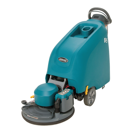
- Page 1 B5/B7 SpeedGleam ® SpeedGleam ® Walk-Behind Battery Burnisher Service Information Manual ® TennantTrue Parts 9011478 North America / International Rev. 00 (01-2014) *9011478* www.tennantco.com www.nobles.com...
- Page 2 Phone: (800) 553- 8033 or (763) 513- 2850 www.tennantco.com www.nobles.com Trojan and HydroLINK are registered trademarks of Trojan Battery Company. Specifications and parts are subject to change without notice. Original Instructions. Copyright E2014 Tennant Company. All rights reserved. Printed in U.S.A.
-
Page 3: Table Of Contents
CONTENTS Contents Page Contents Page Safety PrecautionS . . . . . . . . . . . . . . . . . . . . . . . . 1-1 BurnISh motor . - Page 4 CONTENTS B5/7, SpeedGleam® 5/7 Service Information (1-14)
-
Page 5: Safety Precautions
With pads or accessories not supplied or WARNING: To Reduce the Risk of Fire, approved by Tennant. The use of other Explosion, Electric Shock or Injury: pads may impair safety. In areas with possible falling objects. Read manual before operating machine. - Page 6 Turn machine off and remove key. All repairs must be performed by trained Set parking brake (if equipped). personnel. Block machine wheels. Use Tennant supplied or approved Use tie- down straps to secure machine. replacement parts. Do not modify the machine from its original design.
- Page 7 SAFETY PRECAUTIONS SAFETY LABELS The safety labels appear on the machine in the locations indicated. Replace labels if they are missing or become damaged or illegible. WARNING LABEL - Located on side of control console. WARNING LABEL - Spinning Pad. Keep Hands Away. Located on burnishing head.
- Page 8 SAFETY PRECAUTIONS B5/7, SpeedGleam® 5/7 Service Information (1-14)
- Page 9 GENERAL INFORMATION SECTION Contents Page General InformatIon . . . . . . . . . . . . . . . . . . . . . 2-1 Component LoCator .
-
Page 10: Burnish Motor
GENERAL INFORMATION COMPONENT LOCATOR (B7 ShOwN) Components half-bridge Control module Circuit breakers base Control module D i-Drive Control module (b/SG5*) Dust bag and hepa panel filter burnish head - 20", 24", 27" (b7, 27" shown) burnish motor Contact Switch, pad up/Down head Lift actuator* e-Stop Switch* uSb programming port... - Page 11 GENERAL INFORMATION Note: Note: ecH2O Side Brush ecH2O Enable: ELECTRICAL SChEMATIC SYMBOLS J7-12 Low=SV3 H20 Valve ON J7-10 Low=Turn ON ecH2O ecH2O Pump ON 100% IGN ST Battery Circuit Breaker DPDT Switch Key Switch Fuse Pressure Switch Connected Diode Motor Not Connected Single Continuation Tab Connector...
-
Page 12: Interface Module
P1-2 33/ORA 33/ORA P1-1 POT HIGH 100K PROPEL SPEED LIMIT WIPER_IN J10-1 P3-1 DIGITAL_GND I-DRIVE 13/BLK I-DRIVE PROPEL SYSTEM OPTIONAL ON B5/SpeedGleam 5 CABLE, CHARGER STANDARD ON B7/SpeedGleam 7 13/BLK J2-8 J5-1 J7-8 13/BLK COMM_GND J5-2 WIPER OUT J7-2 J5-3... - Page 13 GENERAL INFORMATION ELECTRICAL SChEMATIC (DRIVE MODEL) - 2 of 2 FUSE-1 1/2 BRIDGE CABLE B+/FUSE ASSY J2-1 J4-1 1/RED 2/BRN 13/BLK 13/BLK 100A J1-1 2/BRN MTR2 MTR, LOW SIDE BURNISHER MOTOR CABLE MOTOR TO 1/2 BRIDGE PCB J3-4 N/C_1 J3-3 SHIELD_GND J3-2 J5-1...
- Page 14 GENERAL INFORMATION ELECTRICAL SChEMATIC (PUSh MODEL) - 1 of 2 B5/SpeedGleam5 (3 x 12 vDC) 36 VOLT CONFIGURATIONS 12 VDC 12 VDC 12 VDC 1/RED 13/BLK OFF BOARD CHARGER CABLE (OPTION) CB-1 1/RED 2.5A 13/BLK CABLE, CHARGER 13/BLK J5-1 J7-8 J2-8 13/BLK COMM_GND...
- Page 15 GENERAL INFORMATION ELECTRICAL SChEMATIC (PUSh MODEL) - 2 of 2 1/2 BRIDGE FUSE-1 CABLE B+/FUSE ASSY J2-1 J4-1 1/RED 2/BRN 13/BLK 13/BLK 100A J1-1 2/BRN MTR2 MTR, LOW SIDE BURNISHER MOTOR CABLE MOTOR TO 1/2 BRIDGE PCB J3-4 N/C_1 J3-3 SHIELD_GND J3-2 J5-1...
- Page 16 GENERAL INFORMATION B5/7, SpeedGleam5/7 OPERATIONAL MATRIX FUNCTION ENABLED DISABLED Burnish Motor - On • Burnish Head Down • Burnish Head Up • Burnish Bail Activated • Burnish Bail Release • Low Battery Voltage (< 32.5 vDC) • Load Current Fault •...
-
Page 17: Fastener Torque
GENERAL INFORMATION FASTENER TORQUE SAE (STANDARD) thread thread headless Square Size Grade 1 Grade 2 Cutting Grade 5 Grade 8 Socket Set head Set Carriage thread Socket & Screws Screws bolts rolling Stainless Steel 4 (.112) (5) - (6 .5) (4) - (6) 5 (.125) (6) - (8) - Page 18 GENERAL INFORMATION B5/ SpeedGleam® 5 GENERAL MAChINE DIMENSIONS/CAPACITIES/PERFORMANCE MODEL (20 in / 510 mm) Push Model (20 in / 510 mm) Drive Model Length 59 in / 1499 mm 59 in / 1499 mm Width 24 .5 in / 622 mm 24 .5 in / 622 mm height 43 in / 1092 mm...
- Page 19 GENERAL INFORMATION B7/ SpeedGleam® 7 GENERAL MAChINE DIMENSIONS/CAPACITIES/PERFORMANCE MODEL (24 in / 610 mm) Drive Model (27 in / 690 mm) Drive Model Length 61 .5 in / 1562 mm 63 in / 1602 mm Width 30 in / 762 mm 31 .5 in / 800 mm height 43 in / 1092 mm...
- Page 20 GENERAL INFORMATION SPECIFICATIONS ELECTRICAL COMPONENTS (For Reference Only) Component measure actuator, Scrub head lift 1 - 3 amps Continuous motor, vacuum fan 5 amps motor, propelling variable to 14 amps, 24 v (transport speed) b5/ SG5 - actuator pressure burnish motor measure Down pressure 1 LeD 42-49 amps Down pressure 2 LeDs 57-64 amps Down pressure 3 LeDs 72-79 amps...
-
Page 21: Machine Dimensions
GENERAL INFORMATION SPECIFICATIONS B5/ SpeedGleam® 5 MACHINE DIMENSIONS 24.5 in / 622 mm 43 in 1,092 mm 59 in / 1,499 mm 2-13 b5/7, SpeedGleam® 5/7 Service information (1-14) - Page 22 GENERAL INFORMATION SPECIFICATIONS B7/ SpeedGleam® 7 MACHINE DIMENSIONS 30 in / 762 mm (24 in / 610 mm Model) 31.5 in / 800 mm (27 in / 690 mm Model) 43 in 1,092 mm 61.5 in / 1,562 mm (24 in / 610 mm Model) 63 in / 1,602 mm (27 in / 690 mm Model) 2-14...
- Page 23 MAINTENANCE SECTION Contents Page Maintenance MaIntenance chart . . . . . . . . . . . . . . . . . . . . . 3-2 after DaIly uSe .
-
Page 24: Maintenance Chart
MAINTENANCE MAINTENANCE CHART Interval/ Person Hours Resp. Description Procedure Batteries Charge Daily Burnishing pad Check, flip or replace Dust collection bag Check, replace Vacuum hose Check, clean Burnishing head dust skirt Check for dry floor finish chunks Weekly Battery electrolyte level Check, add distilled water if low Burnishing head dust skirt Check for wear and damage... -
Page 25: After Daily Use
MAINTENANCE 3. Check vacuum hose for clogging. Clean hose as necessary (Figure 37). MACHINE MAINTENANCE To keep the machine in good working condition, simply perform the following maintenance procedures. FOR SAFETY: Before leaving or servicing machine, stop on level surface, turn off machine, remove key and set parking brake if equipped. -
Page 26: After Every 50 Hours Of Use
MAINTENANCE AFTER EVERY 50 HOURS OF USE AFTER EVERY 100 HOURS OF USE If machine is equipped with the optional HydroLINK 1. Check the dust skirt for wear or damage battery watering system, check the watering hoses and (Figure 40). Replace if worn or damaged. connections for damage and wear (Figure 43). -
Page 27: After Every 1000 Hours Of Use
(Figure 47). Do not remove battery caps when cleaning batteries. Your machine is equipped with either wet/lead- acid or sealed AGM batteries supplied by Tennant. FOR SAFETY: When servicing machine, wear personal protection equipment as needed. Avoid contact with battery acid. -
Page 28: System (Option)
MAINTENANCE 3. Locate the battery fill hose coupler inside the HYDROLINK™ BATTERY WATERING SYSTEM battery compartment. Remove the dust cap and connect the hand pump hose (Figure 49). (OPTION) The following instructions are for models equipped with the HydroLINK battery watering system option. FIG. -
Page 29: Machine Jacking
MAINTENANCE 2. Use a ramp that can support the machine weight and operator and carefully load machine. Do not MACHINE JACKING operate the machine on a ramp incline that exceeds a 19.5% grade level (Figure 54). A winch FOR SAFETY: Before leaving or servicing must be used when ramp incline exceeds a 19.5% machine, stop on level surface, turn off machine grade level. -
Page 30: Storing Machine
MAINTENANCE STORING MACHINE The following steps should be taken when storing the machine for extended periods of time. 1. Charge the batteries before storing machine to prolong the life of the batteries. Recharge batteries every 3 months. 2. Raise the burnishing head off the floor. 3. -
Page 31: Bdi Faults
TROUBLESHOOTING SECTION Contents Page TroubleshooTing BDI FAULTS . . . . . . . . . . . . . . . . . . . . . . . . . . . . . . . . 4-2 SUBSySTem TroUBLeShooTIng . - Page 32 TROUBLESHOOTING BDI (Battery Discharge Indicator) Faults Blinking BDI Fault Cause Correction Base module power supply failure Correct fault condition Actuator circuit open (option) Correct fault condition Burnish motor circuit open Correct fault condition Vacuum motor circuit open (option) Correct fault condition Actuator/Vac breaker tripped (option) Correct fault condition, disconnect battery, reset circuit breaker propel motor breaker tripped (option)
- Page 33 TROUBLESHOOTING BDI (Battery Discharge Indicator) Faults Blinking BDI Fault Cause Correction not Used - reserved for later use Burnish motor voltage loss Correct fault condition propel system iDrive fault (option) Correct fault condition propel motor circuit shorted (option) Correct fault condition Burnish motor hardware over-current Correct fault condition Burnish motor over-current...
-
Page 34: Burnish Motor
TROUBLESHOOTING Burnish Motor Failed to Turn ON HALF-BRIDGE MODULE FUSE-1 100A 2/BRN 13/BLK 1/RED MOTOR, LOW SIDE Burnish Motor RIBBON CABLE TO BASE CONTROLLER Operational Matrix: Enabled Disabled • Burnish head down • Burnish Head Up Burnish • Burnish Bail Release •... - Page 35 TROUBLESHOOTING Burnish Motor Failed to Turn ON sTep AcTion VAlue(s) • Key on See “BDI go to Step #2 • enable burnish motor Faults” in the • Is there a blinking BDI fault present? Troubleshoot- ing section of this manual •...
- Page 36 TROUBLESHOOTING Onboard Battery Charging ON (Optional) B7, SG7 Battery Con guration 6 Volt 6 Volt 6 Volt 6 Volt 6 Volt 6 Volt 12 Volt 12 Volt 12 Volt B5, SG5 Battery Con guration Onboard Battery Charger Hood BLACK Cable Disable 2.5A Switch...
- Page 37 TROUBLESHOOTING Batteries Failed to Charge sTep AcTion VAlue(s) • Key on See “BDI go to Step #2 • Is there a blinking BDI fault present? Faults” in the Troubleshoot- ing section of this manual • Key off go to Step #3 check Ac •...
-
Page 38: Battery Charger (On Board)
TROUBLESHOOTING Off Board Battery Charging ON B7, SG7 Battery Con guration 6 Volt 6 Volt 6 Volt 6 Volt 6 Volt 6 Volt 12 Volt 12 Volt 12 Volt B5, SG5 Battery Con guration Battery Charger Connector Hood Disable 2.5A Switch Not Used N.O. - Page 39 TROUBLESHOOTING Batteries Failed to Charge sTep AcTion VAlue(s) • Key off go to Step #2 check Ac • check Ac power supply Supply circuit • Is the rated Ac supply voltage present? protection • Key off repair or re- go to Step #3 •...
- Page 40 TROUBLESHOOTING Power-Up ON B7, SG7 Battery Con guration 6 Volt 6 Volt 6 Volt 6 Volt 6 Volt 6 Volt B5, SG5 Battery Con guration 12 Volt 12 Volt 12 Volt O -board Battery Charger Interlock Switch (Std) N.O. 5/GRN N.C.
-
Page 41: Power-Up Circuit
TROUBLESHOOTING Machine Failed to Power Up sTep AcTion VAlue(s) • Key on go to Step #2 recharge • Test the total battery voltage using a voltmeter Batteries and • Is the total battery voltage greater than 30 VDc? Test power-Up circuit opera- tion •... -
Page 42: Propel (Option)
TROUBLESHOOTING Propel Subsystem (Optional) B7, SG7 Battery Con guration 6 Volt 6 Volt 6 Volt 6 Volt 6 Volt 6 Volt B5, SG5 Battery Con guration 12 Volt 12 Volt 12 Volt I-Drive Propel Module 8/GRY 13/BLK Propel Motor 24/YEL J5-1 Base 9/WHT P1-5 ON/OFF... - Page 43 TROUBLESHOOTING Machine Failed to Propel sTep AcTion VAlue(s) • Key on See “BDI go to Step #2 • enable propel Faults” in the • Is there a blinking BDI (Battery Discharge Indicator) Troubleshoot- fault present? ing section of this manual •...
-
Page 44: Burnish Head
TROUBLESHOOTING Burnish Head Lift Actuator (Optional) RIBBON CABLE TO HALF-BRIDGE MODULE 16/BLU 13/BLK GND_POWER_A J12-1 J12-7 13/BLK GND_POWER_B 6/BLU J12-8 J10-1 (KEY SWITCH INTERLOCK) 13/BLK GND_RETURN J5-10 EXTEND LIMIT SW. 22/BRN ACT_1 J12-5 RETRACT LIMIT SW. 23/ORA ACT_2 J12-6 Lift Actuator (1-3 Amps) BASE CONTROLLER MODULE... - Page 45 TROUBLESHOOTING Burnish Head Failed to Raise/Lower sTep AcTion VAlue(s) • Key on See “BDI go to Step #2 • enable burnish motor Faults” in the • Is there a blinking BDI (Battery Discharge Indicator) Troubleshoot- fault present? ing section of this manual •...
-
Page 46: Vacuum Fan (Option)
TROUBLESHOOTING Vacuum Fan ON (Optional) RIBBON CABLE TO HALF-BRIDGE MODULE 16/BLU 13/BLK GND_POWER_A J12-1 J12-7 13/BLK GND_POWER_B 6/BLU J12-8 J10-1 (KEY SWITCH INTERLOCK) 13/BLK GND_RETURN J5-10 19/WHT J12-2 25/GRN J12-4 Vacuum Motor (5 Amps) BASE CONTROLLER MODULE Operational Matrix: Enabled Disabled •... -
Page 47: Software
TROUBLESHOOTING Vacuum Fan Failed to Turn ON (Optional) sTep AcTion VAlue(s) • Key on See “BDI go to Step #2 • enable vacuum fan Faults” in the • Is there a blinking BDI (Battery Discharge Indicator) Troubleshoot- fault present? ing section of this manual •... - Page 48 TROUBLESHOOTING 4-18 B5/7, Speedgleam® 5/7 Service Information (1-14)
- Page 49 SERVICE SECTION Contents Page Service Software CoNfIGUratIoN tool . . . . . . . . 5-2 CoNNeCtING to the INterfaCe modUle . . . . . . . . . . . . . . . . . . . . . . . . . . . . 5-2 maChINe CoNfIGUratIoN Software .
-
Page 50: Service
SERVICE launch the software by double clicking the flash SOfTwaRE CONfIguRaTION TOOl drive file “machine Configuration application .exe” and then click “run . ” machine software must be reconfigured if the i-drive or interface modules are replaced in the field or optional fea- tures are installed in the field . -
Page 51: Machine Configuration
SERVICE maChINE CONfIguRaTION SOfTwaRE fEaTuRE dESCRIPTION model Changes model-specific features NOTE: The optional onboard battery charger has a rotary and software listed below: selector switch beneath the front label. The switch must be in the “0” position to enable battery charger CAN-Bus program- drive Type enables self-propel or pad-assist ming via the Machine Configuration Tool. -
Page 52: Battery Charger Setting
SERVICE 4. Using a small standard screwdriver, turn the dial to BATTERY CHARGER SETTINGS the appropriate battery type according to the following chart (Figure 34). The battery charger is set to charge the battery type NOTE: The “0” position is only used when machine is supplied with your machine. -
Page 53: Pad Pressure Setting
SERVICE Down Pressure Setting LED Code f=On PAD PRESSURE SETTING (Models equipped with mechanical pad pressure adjustment) Flashing - Too Low f F F F F For models equipped with mechanical pad pressure f F F F F adjustment, the pad pressure is factory set at the Medium Low F f F F F optimal setting. -
Page 54: Burnish Motor
SERVICE removing burniSh motor tilt burnish head down, release the plastic fasteners and remove motor cover . For SaFetY: before leaving or servicing machine, stop on level surface, turn off machine, remove key and disconnect batteries. Key off and disconnect batteries . remove burnish pad . - Page 55 SERVICE carbon bruSheS remove brush tensioner springs (8) . For SaFetY: before leaving or servicing machine, stop on level surface, turn off machine, remove key and disconnect batteries. Key off and disconnect batteries . remove upper motor cover mounting hardware and and set cover aside .
-
Page 56: Vacuum Fan
SERVICE removing vacuum Fan remove vacuum fan mounting hardware (4) . For SaFetY: before leaving or servicing machine, stop on level surface, turn off machine, remove key and disconnect batteries. Key off and disconnect batteries . open access cover and remove batteries . disconnect vacuum fan from wire harness . -
Page 57: Control Modules
SERVICE remove control module cover . CONTROl mOdulES removing halF-bridge/baSe control moduleS For SaFetY: When servicing machine, disconnect bat- tery connections before working on machine. Key off and batteries disconnected . attach a static wrist strap to the battery (-) terminal to prevent eSd damage to the modules . - Page 58 SERVICE inStalling halF-bridge/baSe control module inStalling i-drive module For SaFetY: When servicing machine, disconnect bat- For SaFetY: When servicing machine, disconnect bat- tery connections before working on machine. tery connections before working on machine. Installation is reverse of removal . Installation is reverse of removal .
- Page 59 SERVICE removing onboard batterY charger For SaFetY: When servicing machine, disconnect bat- tery connections before working on machine. Key off and batteries disconnected . remove t-25 torx mounting screws (2) . remove battery charger mounting hardware (4) . Carefully lower access cover . remove battery charger .
-
Page 60: Interface Module
SERVICE removing interFace module remove t-25 torx mounting screws (2) . For SaFetY: When servicing machine, disconnect bat- tery connections before working on machine. Key off and batteries disconnected . attach a static wrist strap to the battery (-) terminal to prevent eSd damage to the logic board . -
Page 61: Bail Switch Or Potentiometer
SERVICE removing bail SWitch or potentiometer remove cover and set aside . For SaFetY: When servicing machine, disconnect bat- tery connections before working on machine. Key off and batteries disconnected . remove t-25 torx mounting screws (2) . remove rear access cover mounting screws (2) . Carefully separate the touch panel from the console and disconnect all electrical connections . - Page 62 SERVICE remove operator console mounting bolts (2) . 11 . remove screws (4) from front of operator’s console . 12 . remove screws (9) from rear of operator’s console lift up and forward to remove the operator console and separate console assembly . and place console on a work bench .
Need help?
Do you have a question about the SpeedGleam 5 and is the answer not in the manual?
Questions and answers