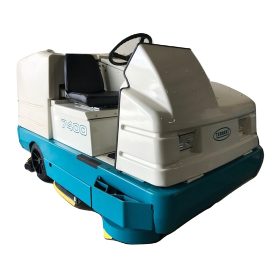
Tennant 7400 Operator's Manual
Rider floor scrubbers
Hide thumbs
Also See for 7400:
- Operator's manual (92 pages) ,
- Operator's manual (88 pages) ,
- Service manual (322 pages)
Table of Contents
Advertisement
Quick Links
Download this manual
See also:
Operator's Manual
Advertisement
Table of Contents

Subscribe to Our Youtube Channel
Related Manuals for Tennant 7400


Summary of Contents for Tennant 7400
- Page 1 7400 Operator Manual MM425 Rev. 10 *mm425* Home Find... Go To..
-
Page 2: Home Find... Go To
This manual is furnished with each new TENNANT Model 7400. It provides necessary operating and preventive maintenance instructions. Read this manual completely and understand the machine before operating or servicing it. This machine will provide excellent service. However, the best results will be obtained at minimum costs if: D The machine is operated with reasonable care. -
Page 3: Table Of Contents
VACUUM WAND ....MACHINE TROUBLESHOOTING ..7400 MM425 (6- -00) Home Find... Go To.. - Page 4 ........7400 MM425 (6- -00) Home...
-
Page 5: Safety Precautions
- - Use cardboard to locate leaking designed for use in those areas. hydraulic fluid under pressure. - - In areas with possible falling objects - - Use Tennant supplied or approved unless equipped with overhead guard. replacement parts. 7400 MM425 (3- -02) Home Find... -
Page 6: Home Find... Go To
380 mm (15 in) or less from the ground. - - Set parking brake after machine is loaded. - - Block machine tires. - - Tie machine down to truck or trailer. 7400 MM425 (3- -02) Home Find... Go To.. - Page 7 EMISSIONS LABEL - - LOCATED ON THE SIDE FOR SAFETY LABEL - - LOCATED ON THE OF THE OPERATOR COMPARTMENT. SIDE OF THE OPERATOR COMPARTMENT. 10783 FLAMMABLE SPILLS LABEL - - LOCATED ON THE SIDE OF THE OPERATOR COMPARTMENT. 7400 MM425 (6- -00) Home Find... Go To..
- Page 8 STRONG VACUUM LABEL - - LOCATED ON ENGINE COMPARTMENT LINTEL. THE VACUUM FAN HOUSING. 10783 FLAMMABLE MATERIALS LABEL - - LOCATED NEXT TO THE SOLUTION TANK COVERS AND ON THE DETERGENT TANK. 7400 MM425 (6- -00) Home Find... Go To..
-
Page 9: Operation
Tennant representative. - Order parts and supplies directly from your authorized Tennant representative. Use the parts manual provided when ordering parts. - After the first 50 hours of operation, follow the recommended procedures stated in the MAINTENANCE CHART. -
Page 10: Machine Components
C. Operator seat D. Engine cover E. Machine front cover F. Solution tank covers G. Solution tanks H. Recovery tank covers Recovery Tank J. Rear squeegee K. Side Squeegee L. Scrub brush access door 7400 MM425 (6- -00) Home Find... Go To.. -
Page 11: Symbol Definitions
Side brush down and on Circuit breaker 8 Rear squeegee down and vacuum on Cover release Detergent flow Hydraulic fluid only Solution flow Gasoline fuel only Scrub brushes down and on Jack-point Engine 7400 MM425 (6- -00) Home Find... Go To.. -
Page 12: Controls And Instruments
R. Engine speed switch S. Steering wheel T. Horn button U. Ignition switch V. Steering column tilt lever W. Circuit breakers X. Solution flow switch Y. Engine choke knob Z. Cover release knob 7400 MM425 (6- -00) Home Find... Go To.. -
Page 13: Operation Of Controls
Reverse: Press the bottom of the directional pedal with the heel of your foot. Neutral: Take your foot off the directional pedal and it will return to the neutral position. 7400 MM425 (6- -00) Home Find... Go To.. -
Page 14: Brake Pedal
CHARGING SYSTEM LIGHT The charging system light comes on when the alternator is not operating within normal range; 13.5 to 14.5 Volts. Stop operating the machine. Locate the problem and have it corrected. 10642 7400 MM425 (6- -00) Home Find... Go To.. -
Page 15: Engine Oil Pressure Light
The maintenance mode light comes on when the control panel diagnostic mode is manually activated. The maintenance mode is for service personnel use only. To clear the diagnostic mode, turn the ignition key all the way counter-clockwise. 10645 7400 MM425 (6- -00) Home Find... Go To.. -
Page 16: Recovery Tank Full Light
The OK light will go out when the scrub or squeegee switch is activated, or the engine speed is changed to (Fast). 10889 7400 MM425 (6- -00) Home Find... Go To.. -
Page 17: Fuel Level Gauge
The hourmeter records the number of hours the machine has been operated. The hourmeter displays the number of hours in tenths of an hour. Use this information to determine machine maintenance intervals. 07765 7400 MM425 (6- -00) Home Find... Go To.. -
Page 18: Est Switch (Option)
NOTE: The side brush will lower and start when the scrubbing operations start. The main scrub 10891 brushes have to be on for the side brush to operate. 7400 MM425 (6- -00) Home Find... Go To.. -
Page 19: Squeegee Switch
NOTE: The rear squeegee will raise and the vacuum fan will shut off after a short delay when the scrubbing operations are shut off. 7400 MM425 (6- -00) Home Find... Go To.. -
Page 20: Detergent Flow Switch (Option)
NOTE: The scrub head and squeegee will raise when the machine travels in reverse. 7400 MM425 (6- -00) Home Find... Go To.. -
Page 21: Engine Speed Switch
Right: Turn the steering wheel to the right. COVER RELEASE KNOB The cover release knob releases the machine front cover latch. To release: Pull out and hold the cover release knob, then pull open the machine cover. 7400 MM425 (6- -00) Home Find... Go To.. -
Page 22: Horn Button
STEERING COLUMN TILT HANDLE The steering wheel tilt handle adjusts the angle of the steering wheel. Adjust: Pull out the tilt handle, move the wheel up or down, and release the tilt handle. 7400 MM425 (6- -00) Home Find... Go To.. -
Page 23: Circuit Breakers
15 A ESt (option) CB-3 15 A Operating lights CB-4 15 A Back-up alarm (option) CB-5 15 A Horn CB-6 Instrument panel CB-7 15 A Scrubbing CB-8 15 A Side brush (option) 7400 MM425 (6- -00) Home Find... Go To.. -
Page 24: Solution Flow Switch
ENGINE CHOKE KNOB The engine choke knob controls the engine choke on gasoline powered machines. On: For cold starting, pull the engine choke knob out. Off: Push the engine choke knob in. 7400 MM425 (6- -00) Home Find... Go To.. -
Page 25: Operator Seat
The recovery tank drain hose is used to drain the recovery tank. Drain the recovery tank by removing the drain hose cap from the tank access cap. Pull out the recovery tank hose and remove the drain hose end cap. 7400 MM425 (6- -00) Home Find... Go To.. -
Page 26: Latches
When scrubbing is finished, drain and clean the recovery tank. If using the ESt system, drain and clean the solution tank, clean the solution outlet filter, and clean the ESt filter. 7400 MM425 (6- -00) Home Find... Go To.. -
Page 27: Pre-Operation Checklist
OPERATION PRE-OPERATION CHECKLIST - Check under the machine for leaks (fuel, oil, coolant, scrubbing solution). - Check the engine air filter indicator. - Check the engine oil level. 7400 MM425 (6- -00) Home Find... Go To.. -
Page 28: Home Find... Go To
OPERATION - Check fuel level. 07764 - Check the brakes and steering for proper operation. - Check the rear squeegee for wear and proper deflection. Check the side squeegees for wear. 7400 MM425 (6- -00) Home Find... Go To.. -
Page 29: Changing An Lpg Fuel Tank
7. Carefully put the filled LPG tank in the machine so that the tank centering pin enters the aligning hole in the tank collar. 8. Fasten the tank hold-down clamp to lock the tank in position. 07812 7400 MM425 (6- -00) Home Find... Go To.. -
Page 30: Home Find... Go To
07813 10. Open the tank service valve slowly and check for leaks. Close the service valve immediately if an LPG leak is found, and tell the appropriate personnel. 07814 7400 MM425 (6- -00) Home Find... Go To.. -
Page 31: Starting The Machine
LPG powered machines: When the engine is cold and exposed to cold temperatures; open the engine cover, press the primer button on the LPG vaporizer, and close the engine cover. 7400 MM425 (6- -00) Home Find... Go To.. -
Page 32: Home Find... Go To
Keep engine properly tuned. 6. Release the machine parking brake. 7. Select the (Fast) engine speed with the engine speed switch. 8. Drive the machine to the solution tank filling area. 10896 7400 MM425 (6- -00) Home Find... Go To.. -
Page 33: Scrubbing And Brush Information
Super abrasive bristle main scrub brush -- Nylon fiber impregnated with abrasive grit to remove stains and soilage. Strong action on any surface, performing well on buildup, grease, or tire marks. 7400 MM425 (6- -00) Home Find... Go To.. -
Page 34: Filling The Tanks
2. Drive the machine to the filling site. 3. Shut the engine off. 4. Set the parking brake. FOR SAFETY: Before leaving or servicing machine; stop on level surface, set parking brake, turn off machine and remove key. 7400 MM425 (6- -00) Home Find... Go To.. -
Page 35: Home Find... Go To
NOTE: If you do not want to use the ESt system, do not put any water in the recovery tank. Turn off the ESt switch. 6. Close the tank covers. 7400 MM425 (6- -00) Home Find... Go To.. -
Page 36: Scrubbing
The engine speed will change to (Fast). 10897 WARNING: Flammable materials or reactive metals can cause an explosion or fire. Do not pickup. 7400 MM425 (6- -00) Home Find... Go To.. -
Page 37: Home Find... Go To
The brush pressure has three positions. Under normal conditions, the brush pressure should be set in the minimum setting. Under heavy grime conditions, the brush pressure should be set in the maximum setting. 10897 7400 MM425 (6- -00) Home Find... Go To.. -
Page 38: Double Scrubbing
The engine speed will remain at (Fast). Drive the machine forward until the vacuum fan shuts off. 10897 7400 MM425 (6- -00) Home Find... Go To.. -
Page 39: Draining And Cleaning The Tanks
1. Stop scrubbing. 2. Drive the machine next to an appropriate disposal site. 3. Shut the engine off. 4. Set the parking brake. 7400 MM425 (6- -00) Home Find... Go To.. -
Page 40: Home Find... Go To
7. Open the recovery tank covers. 8. Spray the inside of the recovery tank with clean water. 9. Remove the large drain cap and flush out the bottom on the recovery tank. 7400 MM425 (6- -00) Home Find... Go To.. -
Page 41: Home Find... Go To
16. Clean the debris screen located at the bottom of the tray. 17. Slide the debris tray into the rear squeegee and tray assembly. 18. Connect the vacuum hose. Swing the assembly back into place and latch. 7400 MM425 (6- -00) Home Find... Go To.. -
Page 42: Stop The Machine
2. Take your foot off the directional pedal. Step on the brake pedal. 3. Select the (Idle) position with the engine speed switch. 10900 4. Set the machine parking brake. 7400 MM425 (6- -00) Home Find... Go To.. -
Page 43: Home Find... Go To
FOR SAFETY: Before leaving or servicing machine; stop on level surface, set parking brake, turn off machine and remove key. 6. LPG powered machines: Close the LPG tank’s liquid service valve. 07810 7400 MM425 (6- -00) Home Find... Go To.. -
Page 44: Post-Operation Checklist
- ESt mode: Drain and clean the solution tank and clean the solution outlet filter. Clean the ESt filter. - Check the vacuum hoses for debris or obstructions. - Remove and clean the debris tray. 7400 MM425 (6- -00) Home Find... Go To.. -
Page 45: Operation On Inclines
The maximum rated incline for scrubbing with the machine is 6_. The maximum rated incline during transport of the machine is 8_. FOR SAFETY: When using machine, go slow on inclines and slippery surfaces. 7400 MM425 (6- -00) Home Find... Go To.. -
Page 46: Options
2. Lower the squeegee and shut the engine off. 10901 3. Set the machine parking brake. FOR SAFETY: Before leaving or servicing machine; stop on level surface, set parking brake, turn off machine and remove key. 7400 MM425 (6- -00) Home Find... Go To.. -
Page 47: Home Find... Go To
5. Put together the wand and the wand hose. 6. Start the engine. 7. Select the (Fast) engine speed with the engine speed switch. 10900 8. Lower the squeegee to turn the vacuum system on. 10901 7400 MM425 (6- -00) Home Find... Go To.. -
Page 48: Home Find... Go To
10. Shut the engine off. 11. Remove the vacuum hose from the squeegee suction hose and connect the squeegee suction hose to the rear squeegee. 12. Put the vacuum wand and hose in the mounting clips. 7400 MM425 (6- -00) Home Find... Go To.. -
Page 49: Machine Troubleshooting
Clogged solution pump or lines. Flush ESt system. solution tank. l ti ESt float stuck. Clean floats of debris. Clogged ESt pump filter. Clean filter. Water levels too low in tanks. Add water. 7400 MM425 (6- -00) Home Find... Go To.. -
Page 50: Maintenance
Check fan belt tension Engine Check and adjust idle speed Check and adjust idle mixture Hydraulic fluid reservoir Check fluid level HYDO Tires Check for damage Rear squeegee Check leveling Rear squeegee casters Lubricate 7400 MM425 (6- -00) Home Find... Go To.. - Page 51 . . . Water and permanent-type ethylene glycol anti-freeze, --34_ C (--30_ F) . . . Special lubricant, Lubriplate EMB grease (TENNANT part no. 01433--1) ..Distilled water NOTE: Also check procedures indicted (H) after the first 50-hours of operation.
-
Page 52: Lubrication
(3.5 qt) including the oil filter. REAR WHEEL BEARINGS Inspect the rear wheel bearings for seal damage, and repack and adjust every 400 hours of operation. Use Lubriplate EMB grease (Tennant part number 01433--1). 7400 MM425 (6- -00) Home Find... Go To.. -
Page 53: Scrub Brush Idler
The front wheel support pivots the front wheel. The front wheel support bearings must be lubricated every 200 hours of operation. Use Lubriplate EMB grease (Tennant part no. 01433--1). SCRUB BRUSH IDLER Each scrub brush idler has one grease fitting. The scrub brush idlers must be lubricated every 100 hours of operation. -
Page 54: Hydraulics
The quality and condition of the hydraulic fluid play a very important role in how well the machine operates. Tennant hydraulic fluid is specially selected to meet the needs of Tennant machines. Tennant hydraulic fluids provide a longer life for the hydraulic components. There are two fluids available for different temperature ranges: Tennant part no. -
Page 55: Hydraulic Hoses
The lower temperature fluid is a thinner fluid for colder temperatures. If a locally-available hydraulic fluid is used, make sure the specifications match Tennant hydraulic fluid specifications. Using substitute fluids can cause premature failure of hydraulic components. ATTENTION! Hydraulic components depend on system hydraulic fluid for internal lubrication. -
Page 56: Engine
FOR SAFETY: When servicing machine, wear eye and ear protection when using pressurized air or water. Flush the radiator and the cooling system every 800 hours of operation, using a dependable cleaning compound. 7400 MM425 (6- -00) Home Find... Go To.. -
Page 57: Air Filter Indicator
Replace the air filter element only when the air filter indicator shows restriction in the air intake system. Do not remove the air filter element from the housing unless it is restricting air flow. 02492 7400 MM425 (6- -00) Home Find... Go To.. -
Page 58: Fuel Filter
50 hours of operation and every 400 hours there after. CRANKCASE VENTILATION SYSTEM Replace the oil fill cap/PCV breather and clean the crankcase ventilation hose after every 400 hours of operation. 7400 MM425 (3- -02) Home Find... Go To.. -
Page 59: Battery
The chain is attached to the machine frame just in front of the scrub head, on the left side of the machine. Make sure the chain is touching the floor at all times. 7400 MM425 (6- -00) Home Find... Go To.. -
Page 60: Scrub Brushes
Lower the scrub head with the scrub switch. 5. Turn off the ignition switch. FOR SAFETY: Before leaving or servicing machine; stop on level surface, set parking brake, turn off machine and remove key. 7400 MM425 (3- -01) Home Find... Go To.. - Page 61 V-patterns on the brushes pointing towards each other. Slide the brushes onto the brush drive plugs. NOTE: The scrub head may need to be raise a little to insert new brushes. 7400 MM425 (3- -01) Home Find... Go To..
-
Page 62: Checking And Adjusting Scrub Brush Pattern
6. Observe the width of the brush pattern. If the brush patterns have parallel sides and are the same width, the brushes do not need taper adjustment. 10355 7400 MM425 (3- -01) Home Find... Go To.. - Page 63 A. Lengthen or shorten the leveling rods on both sides of the scrub head. Lengthening the rods will increase the rear brush pattern width. Shortening the rods will will increase the front brush pattern. 7400 MM425 (6- -00) Home Find... Go To..
-
Page 64: Solution System
Clean the debris screen located at the bottom of the tray. Slide the debris tray into the rear squeegee and tray assembly. Connect the vacuum hose. Swing the assembly back into place and latch. 7400 MM425 (6- -00) Home Find... Go To.. -
Page 65: Squeegees
15 to 20 mm (0.50 to 0.75 in). The front 0.25 in) (0.50 to slotted squeegee blade should contact the 0.75 in) floor with a slight deflection, 5 mm (0.13 to 0.25 in). 10918 7400 MM425 (6- -00) Home Find... Go To.. -
Page 66: Leveling The Rear Squeegee
3. Look at the deflection over the full length of the squeegee blade. 4. If the deflection is not the same over the full length of the blade, loosen the locking nut on the two rear squeegee balljoints. 7400 MM425 (6- -00) Home Find... Go To.. - Page 67 6. Tighten the locking nuts. 7. Start the engine and drive the machine forward again to check the squeegee blade deflection. 8. Readjust the squeegee blade deflection if necessary. 7400 MM425 (6- -00) Home Find... Go To..
-
Page 68: Squeegee Blades
FOR SAFETY: Before leaving or servicing machine; stop on level surface, set parking brake, turn off machine and remove key. 3. Open the retaining band clamp and remove the squeegee blade. 7400 MM425 (6- -00) Home Find... Go To.. -
Page 69: Side Squeegees
059420 6. Replace the retainer bracket, deflector, clevis pin, and cotter pin. 7. Repeat for the side squeegee on the other side of the scrub head. 7400 MM425 (6- -00) Home Find... Go To.. -
Page 70: Skirts And Seals
A skirt is mounted on each side of the scrub head. Check the skirts for wear or damage every 100 hours of operation. COVER SEALS Check the solution and recovery tank cover seals for wear or damage every 100 hours of operation 7400 MM425 (6- -00) Home Find... Go To.. -
Page 71: Brakes And Tires
Torque the front wheel nuts twice in the pattern shown to 122 to 149 Nm (90 to 110 ft lb) after the first 50-hours of operation, and every 800 hours there after. 7400 MM425 (12- -02) Home Find... Go To.. -
Page 72: Pushing, Towing, And Transporting The Machine
Turn the bypass valve 90_ from the normal position before pushing or towing the machine. The illustration shows the bypass valve in the pushing or towing position. 7400 MM425 (6- -00) Home Find... Go To.. -
Page 73: Transporting The Machine
Do not drive the machine onto the truck or trailer unless the loading surface is horizontal AND is 380 mm (15 in) or less from the ground. 7400 MM425 (6- -00) Home Find... Go To.. - Page 74 Do not drive the machine off the truck or trailer unless the loading surface is horizontal AND 380 mm (15 in) or less from the ground. 7400 MM425 (6- -00) Home Find... Go To..
-
Page 75: Machine Jacking
Before storing the machine for an extended period of time, the machine needs to be prepped to lessen the chance of rust, sludge, and other undesirable deposits from forming. Contact your Tennant service personnel. 7400 MM425 (3- -01) Home Find... Go To.. -
Page 76: Options
4. Line up the new side brush drive socket with the drive hub. 5. Lift and snap the side brush onto the drive hub. 6. Check to make sure the brush is securely mounted on the drive hub. 7400 MM425 (6- -00) Home Find... Go To.. -
Page 77: Replacing The Squeegee Blade
8. Install the side brush guard. SIDE BRUSH SKIRT The side brush skirt is located behind the squeegee blade. Check the skirt for wear and damage every 100 hours of operation. 7400 MM425 (6- -00) Home Find... Go To.. -
Page 78: Specifications
3190 mm (125.5 in) Minimum turning radius, right 2660 mm (104.75 in) Minimum turning radius, left 2030 mm (79.75 in) Maximum rated incline for scrubbing Maximum rated incline for transport of machine 7400 MM425 (6- -00) Home Find... Go To.. -
Page 79: Power Type
HYDRAULIC SYSTEM System Capacity Fluid Type TENNANT part no. 65869 -- above 7_ C (45_ F) Hydraulic reservoir 38 L (10 gal) TENNANT part no. 65870 -- below 7_ C (45_ F) Hydraulic total 74 L (19.5 gal) -
Page 80: Machine Dimensions
(66.4 in) 1327 mm (52.25 in) 1610 mm (63.4 in) 1525 mm (60 in) 1483 mm (58.4 in) 2045 mm (80.5 in) 1475 mm (58 in) 1260 mm (49.6 in) 10919 MACHINE DIMENSIONS 7400 MM425 (6- -00) Home Find... Go To.. -
Page 81: Index
Steering column tilt handles, 20 Choke, Engine, 22 Steering wheel, 19 Circuit breakers, 21 Cover release knob, 19 Covers Engine, Latch, 24 Seals, 68 Solution tank, Latch, 24 Crankcase ventilation system, 56 7400 MM425 (6- -00) Home Find... Go To.. - Page 82 Engine choke knob, 22 Reservoir, 52 Engine oil pressure light, 13 System specifications, 77 Engine speed switch, 19 Engine water temperature light, 13 ES filter, 62 Ignition switch, 20 ES switch, 16 Incline, Rated, 43 7400 MM425 (6- -00) Home Find... Go To..
- Page 83 Rear squeegee casters, 51 Recommended, 7 Rear wheel bearings, 50 Maintenance chart, 48 Recovery tank, 62 Maintenance mode light, 13 Drain and clean, 42 Drain hose, 23 Motors, Propelling, 53 Full light, 14 7400 MM425 (6- -00) Home Find... Go To..
- Page 84 Stop scrubbing, 36 Side squeegees, 67 Stop the machine, 40 Replacing blades, 67 Storing machine, 73 Skirts, 68–70 Scrub head, 68 Solution, Tank drain hose, 23 Solution flow switch, 22 Solution outlet filter, 62 7400 MM425 (6- -00) Home Find... Go To..
- Page 85 Towing machine, 70 Transporting machine, 70 Transporting the machine, 71 Travel speed, 76 Tray, Debris, 62–65 Troubleshooting, 47–49 Vacuum fan, Switch, 17 Vacuum hoses, Check, 42 Vacuum wand, 44–46 Valve tappet clearance, 56 7400 MM425 (6- -00) Home Find... Go To..
- Page 86 INDEX 7400 MM425 (6- -00) Home Find... Go To..
Need help?
Do you have a question about the 7400 and is the answer not in the manual?
Questions and answers