Table of Contents
Advertisement
Quick Links
Advertisement
Table of Contents

Subscribe to Our Youtube Channel
Related Manuals for Altusen SN0116


Summary of Contents for Altusen SN0116
- Page 1 Serial Over the NET™ SN0108 / SN0116 User Manual www.altusen.com.tw...
-
Page 2: Fcc Information
SN0108 / SN0116 User Manual FCC Information This is an FCC Class A product. In a domestic environment this product may cause radio interference in which case the user may be required to take adequate measures. This equipment has been tested and found to comply with the limits for a Class A digital device, pursuant to Part 15 of the FCC Rules. -
Page 3: User Information
SN0108 / SN0116 User Manual User Information Online Registration Be sure to register your product at our online support center: International http://support.aten.com North America ATEN TECH http://www.aten-usa.com/product_registration ATEN NJ http://support.aten.com Telephone Support For telephone support, call this number: International 886-2-8692-6959... -
Page 4: Package Contents
SN0108 / SN0116 User Manual Package Contents The SN0108 / SN0116 package consists of: 1SN0108, SN0116, SN0108D, or SN0116D 1Power Cord (SN0108 or SN0116) 1Rack Mount Kit (Brackets and Phillips head hex M3 x 8 screws) 1Foot Pad Set (4 pcs.) -
Page 5: Table Of Contents
Rack Mounting ......... . 10 SN0108 / SN0116 PC Installation ....... 11 SN0108D / SN0116D PC Installation . - Page 6 SN0108 / SN0116 User Manual Chapter 4. Administration Working Environment Configuration ......21 General .
- Page 7 SN0108 / SN0116 User Manual Chapter 6. Out of Band Operation Overview ..........53 HyperTerminal.
- Page 8 SN0108 / SN0116 ........
-
Page 9: About This Manual
SN0108 / SN0116 installation. Chapter 6, Out of Band Operation, describes how to set up the various serial port methods that can be used to access the SN0108 / SN0116 when the network is unavailable. -
Page 10: Conventions
For information about all ALTUSEN products and how they can help you connect without limits, visit ALTUSEN on the Web or contact an ALTUSEN Authorized Reseller. Visit ALTUSEN on the Web for a list of locations and telephone numbers International – http://www.aten.com... -
Page 11: Chapter 1. Introduction
Telnet or SSH TCP/IP connection. Up to 8 (SN0108) or 16 (SN0116) Users can log in at the same time from any computer connected to the Internet, whether down the hall, or half way around the world. -
Page 12: Requirements
A choice of browser based GUI, Telnet (SSH), and VT console terminal sessions make configuration and operation smooth and convenient. The SN0108 / SN0116's firmware is upgradeable over the Net, so you can stay current with the latest improvements simply by downloading updates from our website. -
Page 13: Features
Remote serial access over the Internet for up to 8 (SN0108) or 16 (SN0116) servers or other serial IT devices Works in tandem with other Altusen/Aten appliances - such as the PN0108 and PN9108 - allowing administrators to manage a wide range... - Page 14 SN0108 / SN0116 User Manual Serial Connectivity: VT320 support – backward compatible to VT52 (VT52, 100, 220) Hardware and software flow control Real COM port support* Raw TCP Mode support with file-based sessions Alarms and Alerts: Client applications Buzzer SNMP Traps...
-
Page 15: Components
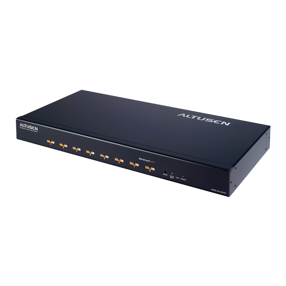
Chapter 1. Introduction Components SN0108 / SN0108D Front Panel 2 3 4 5 SN0116 / SN0116D Front Panel 2 3 4 5 Component Description Port LEDs A Port LED lights to indicate the device attached to its corresponding port is online. The LED flashes when data is being transmitted through its corresponding port. -
Page 16: Sn0108 / Sn0116 Rear Panel (Ac Power)
This is a standard rocker switch that powers the SN0108 / SN0116 on and off. LAN Port The Ethernet cable that connects the SN0108 / SN0116 to the Internet plugs in here. Serial Ports The Cat 5 cables that connect to the RJ45 to Serial adapters plug in here. -
Page 17: Sn0108D / Sn0116D Rear Panel (Dc Power)
Chapter 1. Introduction SN0108D / SN0116D Rear Panel (DC Power) Component Description Grounding Attach the wire to ground this device here. Terminal DC Terminal The electric leads from your power source connect to this Block DC terminal block. Power Switch This is a standard rocker switch that powers the SN0108D / SN0116D on and off. - Page 18 SN0108 / SN0116 User Manual This Page Intentionally Left Blank...
-
Page 19: Chapter 2. Hardware Setup
2. Make sure that power to all the devices you will be connecting up have been turned off. Stacking and Mounting The SN0108 / SN0116 can be placed on the desktop or it can be rack mounted, as described in the sections that follow. Stacking To place the SN0108 / SN0116 on the desktop stick the self-adhesive footpads that came with your package to the unit's bottom panel at the four corners. -
Page 20: Rack Mounting
SN0108 / SN0116 User Manual Rack Mounting The SN0108 / SN0116 can be mounted in a 1U system rack. The mounting brackets can screw into either the front or the back of the unit so that it can attach to the front or the back of the rack. To rack mount the unit: 1. -
Page 21: Sn0108 / Sn0116 Pc Installation
Note: This step is optional. 4. Plug the cable that connects the SN0108 / SN0116 to the network or the Internet into its LAN port. 5. Use the AC power cord provided with this package to connect the SN0108 / SN0116's Power Socket to an AC power source. - Page 22 SN0108 / SN0116 User Manual SN0108 / SN0116 PC Installation Diagram: SA0142 (DB9-M, DTE - DCE) (DB9, DCE) Modem SA0141 (DB9-F, DTE - DTE) (DB9, DTE)
-
Page 23: Sn0108D / Sn0116D Pc Installation
Chapter 2. Hardware Setup SN0108D / SN0116D PC Installation Refer to the Installation Diagram on page 14 (the numbers in the diagram correspond to the numbers of the steps), as you do the following: 1. For each server or serial device, plug an RJ45 to Serial adapter into its serial port. - Page 24 SN0108 / SN0116 User Manual SN0108D / SN0116D PC Installation Diagram: SA0142 (DB9-M, DTE - DCE) (DB9, DCE) Modem +/- 36 – 75V SA0141 (DB9-F, DTE - DTE) (DB9, DTE)
-
Page 25: Sn0108 / Sn0116 Sun Fire V100 Server Installation
(see Chapter 6), refer to step 3 of the PC installation procedure (see page 11). 4. Plug the cable that connects the SN0108 / SN0116 to the network or the Internet into its LAN port. 5. Use the AC power cord provided with this package to connect the SN0108 / SN0116's Power Socket to an AC power source. - Page 26 SN0108 / SN0116 User Manual SN0108 / SN0116 Sun Fire V100 Server Installation Diagram SunFire V100 Server SA0141 SA0142...
-
Page 27: Sn0108D / Sn0116D Sun Fire V100 Server Installation
Chapter 2. Hardware Setup SN0108D / SN0116D Sun Fire V100 Server Installation For each Sun Fire V100 server you wish to install, refer to the Installation Diagram on page 18 (the numbers in the diagram correspond to the numbers of the steps), as you do the following: 1. - Page 28 SN0108 / SN0116 User Manual SN0108D / SN0116DSun Fire V100 Server Installation Diagram SunFire V100 Server SA0141 SA0142 +/- 36 – 75V...
-
Page 29: Chapter 3. Browser Login
Logging In SN0108 / SN0116 operation is Internet browser based. To begin: 1. Open your browser and specify the IP address of the SN0108 / SN0116 you want to access in the browser's URL location bar. Note: 1. Get the IP address from the SN0108 / SN0116 administrator. -
Page 30: The Sn0108 / Sn0116 Main Screen
Note: Be sure to click the Logout icon when you end your session. The bar along the left side is used to configure and control access to each of the SN0108 / SN0116's COM ports. The functions of each of the buttons is described in Chapter 5. -
Page 31: Chapter 4. Administration
Chapter 4 Administration Working Environment Configuration The icon bar across the top of the SN0108 / SN0116 web page is used by the administrator to configure its working environment. An explanation of the functions is given in the sections that follow. -
Page 32: Administrator
System Information The System Information section allows you to provide a name and description for the SN0108 / SN0116 Station. Providing a Station Name and Station Description is optional, but makes it convenient to differentiate the Stations in large, multistation installations. -
Page 33: Network
89, for IP Installer details). Note: If you choose View Only, the utility will be enabled as far as showing the SN0108 / SN0116 in the Device List, but you will not be able to use it to assign IP addresses. -
Page 34: Ip Address
SN0108 / SN0116 User Manual IP Address The default is for a fixed IP address. To give the SN0108 / SN0116 a fixed IP address, fill in the Primary IP to Alternate DNS Server fields with values appropriate to the network you are on. -
Page 35: Anms
It is divided into three main panels, as described below: CC Management Settings: If you want to allow authorization for the SN0108 / SN0116 through a CC (Control Center) server, check Enable CC Management and fill in the CC Server’s IP address and the port that it listens on in the appropriate fields. - Page 36 3. Key the Shared Secret character string that you want to use for authentication between the SN0108 / SN0116 and the RADIUS Server. 4. Set the time in seconds that the SN0108 / SN0116 waits for a RADIUS server reply before it times out in the Timeout field.
-
Page 37: Snmp Settings
SNMP trap events in the SNMP Manager fields. 5. When you have finished making all your entries, click Save, to save them. Note: MIB definitions for the SN0108 / SN0116 are provided on the CD that came with this package. -
Page 38: Oobc
3. Specify the IP address of the device that will connect to the SN0108 / SN0116 in the ClientIP field. 4. Click Update to save the information. The various ways to access the SN0108 / SN0116 with an OOB connection, are described in Chapter 6. -
Page 39: Date / Time
When you click the Date / Time icon, the following dialog box appears: The date and time that the SN0108 / SN0116 is currently set to appear in the upper section. The large middle section offers three methods to set new date... -
Page 40: Firmware
To upgrade your firmware, do the following: 1. From your computer, go to our Internet support site and choose the SN0108 / SN0116 to get a list of available Firmware Upgrade Packages. 2. Choose the Firmware Upgrade Package you want to install (usually the most recent), and download it to your computer. -
Page 41: Device Management Configuration
Chapter 4. Administration Device Management Configuration The buttons in the bar along the left side of the SN0108 / SN0116 web page are used to manage and access the devices connected to the SN0108 / SN0116's COM ports. This section discusses the functions available to administrators and, in the case of port configuration, users with configuration permission. -
Page 42: Property Settings
Meaning Port ID Each port on the SN0108 / SN0116 has a port ID number (COM1 - COM8 for the SN0108, or COM1 - COM16 for the SN0116). The Port ID field displays the number of the port that is being configured. - Page 43 Chapter 4. Administration (Continued from previous page.) Setting Meaning Parity This bit checks the integrity of the transmitted data. Choices are: Even, Odd, None, Mark, and Space. Set this to match the parity setting of the connected device. Default is None (which is the default for the majority of serial devices).
- Page 44 The choices are: Console Management: In this mode, users establish a Telnet or SSH session under the SN0108 / SN0116 to manage a server or serial device connected to the port. Users can log in using the browser Telnet function, a direct Telnet session, SSH or PuTTY.
-
Page 45: Alert Settings
SN0108 / SN0116's ports. When a device has a problem - such as a critical error that requires a reboot - debug messages can be sent through its COM port. -
Page 46: User Manager
SN0108 / SN0116 User Manual 3. Enable the Enable report to the following address checkbox, and key in the IP address of your SMTP server. 4. If your server requires authentication, put a check in the My server requires authentication checkbox. -
Page 47: Deleting An Account
Chapter 4. Administration If user accounts have been set up, the User Manager dialog box appears: This dialog box allows the administrator to add, delete, and edit user accounts. Up to 15 user accounts can be established. Operators must provide the Usernames and Passwords established here, in order to log in. -
Page 48: Editing An Account
SN0108 / SN0116 User Manual 4. If you want the user to have Port Configuration permission, put a check in the Port Config Permission checkbox. Otherwise, leave it blank. Note: 1. Port Configuration is where the Port Numbers and Names that appear in this dialog are set. -
Page 49: Direct Access
Once specific IP addresses are entered here, however, only users logging in to the SN0108 / SN0116 from one of those IP addresses can have access to the RAW TCP or Real COM ports without having to specify a Username and Password. -
Page 50: Session Info
Clicking the Session Info button brings up the Active Sessions display: This display lets the administrator see at a glance all the users currently logged into the SN0108 / SN0116, and provides information about each of their sessions. It also gives the administrator the option of forcing a user logout by selecting... -
Page 51: Sys Info
Chapter 4. Administration Sys Info The System Information dialog box provides information about all aspects of the SN0108 / SN0116's configuration:... -
Page 52: Log
Clicking the Log button brings up the Event Log dialog box: The SN0108 / SN0116 maintains a log file of the events that take place on it. This dialog box allows you to select the range of events you wish to view: Choose Today then click OK to see a listing of only today's events. - Page 53 Chapter 4. Administration (Continued from previous page.) Once you make a choice and click OK an Event Log List, similar to the one below, appears: When you have finished viewing the event list: To return to the Event Log dialog box, click Back. To erase the contents of the entire log file, click Clear ALL Log.
- Page 54 SN0108 / SN0116 User Manual This Page Intentionally Left Blank...
-
Page 55: Chapter 5. Browser Operation
Once you have logged in and the Main Screen appears (see The SN0108 / SN0116 Main Screen, page 20).The bar along the left side is used to configure and control access to each of the SN0108 / SN0116's COM ports. The functions... - Page 56 Administrator This page allows the administrator to see Only information about all the users who are currently logged into the SN0108 / SN0116 (see p. 40) Administrator This page shows information about the SN0108 / Only SN0116's configuration (see p. 41)
-
Page 57: Telnet
Chapter 5. Browser Operation Telnet To access any of the device attached to the SN0108 / SN0116's COM ports, click the Telnet button. A screen similar to the one below appears: 1. Select the port you would like to access. - Page 58 SN0108 / SN0116 User Manual 3. To access the device connected to the port, click Connect. The SN0108 / SN0116 opens a Telnet session and a screen similar to the one below appears: 4. If you are connected to a computer and want to go to a terminal session or command line to operate it, Press [Enter].
- Page 59 Chapter 5. Browser Operation (Continued from previous page.) 6. To display the Suspend Menu, Press [Ctrl+x]. Where x represents the Suspend Character set by the Administrator (see the Property Settings dialog box under Port Configuration, p. 32). The screen will prompt you as to the correct character. In this example, it is [Ctrl+D] (see the prompt on the previous screenshot).
- Page 60 SN0108 / SN0116 User Manual The Main Menu is the text based equivalent of the browser configuration and control functions. The descriptions and explanations for the Browser Operations apply to the submenu functions presented here, as well. Note: 1. As with the browser version, access to many of these submenus are restricted to the administrator or users with configuration permission.
-
Page 61: Port Configuration
Chapter 5. Browser Operation Port Configuration Since only the administrator and users with port configuration permission can access this function, it is discussed in the Administration chapter (seePort Config, page 31). User Manager For users, clicking the User Manager button brings up their User Information dialog box: They can use this dialog box to change their password and Comments information... - Page 62 SN0108 / SN0116 User Manual This Page Intentionally Left Blank...
-
Page 63: Overview
Out of Band Operation Overview In case the network goes down, or the SN0108 / SN0116 cannot be accessed with the usual browser based method for some other reason, the SN0108 / SN0116 can be reached via several additional Out of Band (OOB) methods. - Page 64 SN0108 / SN0116 User Manual 2. On your PC, run the HyperTerminal program: Start → Programs → Accessories → Communications → HyperTerminal → Hypertrm.exe The following dialog box appears: 3. Key a name to describe the connection in the Name field (we chose Com1Test);...
- Page 65 COM1 on your PC), then click OK. A Port Setting dialog box similar to the one below comes up: 5. For OOBC connections, the SN0108 / SN0116's serial port settings and the computer's COM port settings must be the same. Change the settings in your dialog box (if necessary), so that they match the SN0108 / SN0116's Console Port settings (seePort Config, page 31, for details), then click OK.
- Page 66 SN0108 / SN0116 User Manual 6. When the HyperTerminal screen appears, open the File menu and select: Properties → Settings. The following dialog box displays: 7. Change the settings (if necessary), so that they match the settings shown in the dialog box, then click ASCII Setup... The ASCII Setup dialog box comes up: 8.
-
Page 67: Logging In
This completes the HyperTerminal setup. For Windows NT, 2000, XP and Windows Server 2003 systems, a HyperTerminal icon that connects you to the SN0108 / SN0116 is created on the desktop. For Windows 98 and ME, you must access HyperTerminal from the Windows Start Menu. -
Page 68: Indirect Hyperterminal Connection
(pin 2 to pin 2; pin 3 to pin 3) to connect the computer to the modem. On the SN0108 / SN0116 side, use Cat 5 cable and an RJ-45 to Serial adapter to connect a modem to any of its serial ports (see theSN0108D / SN0116D PC Installation Diagram:, page 14). -
Page 69: Final Check
This completes the HyperTerminal setup. For Windows NT, 2000, XP and Windows Server 2003 systems, a HyperTerminal icon that connects you to the SN0108 / SN0116 is created on the desktop. For Windows 98 and ME, you must access HyperTerminal from the Windows Start Menu. -
Page 70: Logging In
2. In the VT100 terminal window, key in: atdt [modem telephone number] [Enter] The terminal responds with: CONNECT115200 3. Wait at least 60 seconds, then key in: [Ctrl+D] 4. Key in your Username and Password to bring up the SN0108 / SN0116's Main Menu. -
Page 71: Ppp (Dial In) Connection
1. Use Ethernet cable a DTE-to-DTE adapter to connect one of the SN0108 / SN0116's serial ports to a COM port on a PC (refer to SN0108 / SN0116 PC Installation, page 11 or SN0108D / SN0116D PC Installation, page 13, if necessary). - Page 72 SN0108 / SN0116 User Manual 4. In the Modem Properties dialog box that comes up change the dialog box settings (if necessary), so that the COM port is correct, then click OK. 5. Click the Connection tab to see the connection setup page: 6.
- Page 73 9. Key in anything you like for these fields, then click Next. 10. Click Finish. A new icon that you can use to connect to the SN0108 / SN0116 is created in the Dial-up Network folder. This completes the Direct Dial In setup.
-
Page 74: Finishing Up
Finishing Up: The SN0108 / SN0116's serial port settings and the computer's COM port settings must be the same. Change the SN0108 / SN0116's settings for the port you are connecting the computer to (seePort Config, page 31), so that they... -
Page 75: Indirect Ppp Connection
3. For Step 9, key in the SN0108 / SN0116's modem telephone number in the fields provided, then click Next. 4. Click Finish. A new icon that you can use to connect to the SN0108 / SN0116 is created in the Dial-up Network folder. This completes the Indirect Dial In setup. -
Page 76: Final Check
2. Key in your Username and Password; click Connect and wait for the Authentication procedure to complete (be patient, it may take a few moments). 3. Use Telnet, SSH, or your browser to access the SN0108 / SN0116 the same way as if you were accessing it over the net. -
Page 77: Telnet
Telnet Logging In 1. On your computer, open a terminal (command line) session. 2. At the prompt, key in the SN0108 / SN0116's IP Address in the following way: telnet [IP Address] Note: The default telnet port is 23. If that port is already being used, up to 16 additional users can log in by adding a port number (from 5000 to 5015) to the login command. -
Page 78: Ssh
SN0108 / SN0116 User Manual Terminal Session (Linux): 1. Open a terminal (command line) on your computer. 2. At the prompt, key in your SN0108 / SN0116 Username and the SN0108 / SN0116's IP Address in the following way: SSH [username@IP Address] Note: The default SSH port is 22. -
Page 79: Third Party Utility (Windows)
You must close PuTTY and start over. Once an SSH connection to the device is established, the SN0108 / SN0116 Main Menu comes up. This menu is the same as the main menu that appears... - Page 80 SN0108 / SN0116 User Manual This Page Intentionally Left Blank...
-
Page 81: Real Com Port Management
COM port on the local computer. Data transmission between the device and the local computer takes place over the virtual COM port to the SN0108 / SN0116. This mode is useful with serial devices such POS terminals, Bar Code Readers, Serial printers, etc. -
Page 82: Windows 98 Installation
Windows 98 Installation To install the Windows 98 and higher driver, do the following: 1. On the software CD that came with your SN0108 / SN0116 package, locate the file: SN0116 Virtual Port for Win98 vxxx.exe. Note: The vxxx specified above stands for the driver’s version number. The file on the CD will show an actual version number. -
Page 83: Linux Installation
/root/temp Note: Under Linux, all input is case sensitive 2. On the software CD that came with your SN0108 / SN0116 package, locate the file AtenVPInstall_vxxx.tgz (or download it from our website), and copy it into the temp directory you just created. -
Page 84: Real Com Port Management - Windows
SN0108 / SN0116 User Manual Real COM Port Management – Windows The Virtual Port Management Utility provides a convenient interface to COM port mapping. When you run the Virtual Serial Port Manager program (Start → → Virtual Port Management Utility... -
Page 85: Menu And Toolbar
Chapter 7. Real COM Port Management Menu and Toolbar The Virtual Port Management Utility menu and toolbar have the same captions and functions. Users can either click the menu items or buttons to invoke the desired function, as shown in the table, below: Item Action Enum Targets... -
Page 86: Target List
SN0108 / SN0116 User Manual Target List The left side panel displays all the devices that were found with the Enumeration function, as well as any devices that were manually added with the Target Information fields. Note: Double clicking an item in the list invokes the same function as selecting Enum Ports–which displays the numbers and working modes... -
Page 87: Port List
Chapter 7. Real COM Port Management Port List This list displays the port information of the selected target (only one target can be selected at a time). The left column lists the target’s port numbers, the second column shows the COM port it is mapped to (if any), the third column shows its working mode, and the right column shows its status. -
Page 88: Mapped Com Ports
SN0108 / SN0116 User Manual Mapped COM Ports This panel displays the mapped COM ports, showing the device and port that each mapped one is derived from. The list is generated as soon as the application starts, and is dynamically updated whenever the mapped COM port configuration changes as a result of installations and removals. -
Page 89: Port Unmapping
Chapter 7. Real COM Port Management 3. Click OK to complete the operation. Note: 1. If a range of ports was selected, and Map consecutively is enabled, the COM ports are mapped to the Target ports in sequence based on the port numbers. -
Page 90: Real Com Port Management - Linux
SN0108 / SN0116 User Manual Real COM Port Management – Linux Mapping/Unmapping Virtual Ports To map or unmap virtual ports, do the following: 1. As root, go to the /usr/lib/AtenVPort directory. 2. Issue the following command: /AtenVPMapping The process can run in either Interactive mode or Fast mode. With Interactive mode, users don’t specify any parameters on the command line. -
Page 91: Appendix
Appendix Safety Instructions General Read all of these instructions. Save them for future reference. Follow all warnings and instructions marked on the device. Do not place the device on any unstable surface (cart, stand, table, etc.). If the device falls, serious damage will result. Do not use the device near water. - Page 92 SN0108 / SN0116 User Manual To help protect your system from sudden, transient increases and decreases in electrical power, use a surge suppressor, line conditioner, or uninterruptible power supply (UPS). Position system cables and power cables carefully; Be sure that nothing rests on any cables.
-
Page 93: Dc Power
Chapter . DC Power The system relies on the protective devices in the building installation for protection against short-circuit, overcurrent, and earth (grounding) fault. Ensure that the protective devices in the building installation are properly rated to protect the system, and that they comply with national and local codes. -
Page 94: Rack Mounting
SN0108 / SN0116 User Manual Rack Mounting Before working on the rack, make sure that the stabilizers are secured to the rack, extended to the floor, and that the full weight of the rack rests on the floor. Install front and side stabilizers on a single rack or front stabilizers for joined multiple racks before working on the rack. -
Page 95: Technical Support
Chapter . Technical Support Technical support is available both by email and online (with a browser over the web): International Email Support support@aten.com Online Technical Support http://support.aten.com Support Troubleshooting http://www.aten.com Documentation Software Updates Telephone Support 886-2-8692-6959 North America Email Support ATEN TECH support@aten-usa.com ATEN NJ sales@aten.com... -
Page 96: Specifications
SN0108 / SN0116 User Manual Specifications SN0108 / SN0116 Function SN0108 SN0116 Serial To Devices 8 x Serial Device 16 x Serial Device Connectors Jacks Jacks To LAN 1 x RJ-45 Power Connector 1 x 3-prong AC Socket LEDs Link [LAN]... -
Page 97: Sn0108D / Sn0116D
Chapter . SN0108D / SN0116D Function SN0108 SN0116 Serial To Devices 8 x Serial Device 16 x Serial Device Connectors Jacks Jacks To LAN 1 x RJ-45 Power Connector DC Terminal LEDs Link [LAN] 1 x Green 10/100 Mbps 1 x Orange/Green... -
Page 98: Administrator Login Failure
4. When the Link and 10/100Mbps LEDs flash, power off the switch. 5. Remove the jumper cap from J6. 6. Close the housing and start the SN0108 / SN0116 back up. After you start back up, you can use the default Username and Password... -
Page 99: Ip Address Determination
If you are an administrator logging in for the first time, you need to access the SN0108 / SN0116 in order to give it an IP address that users can connect to. There are three methods to choose from. In each case, your computer must be on the same network segment as the SN0108 / SN0116.After you have... -
Page 100: Method 2
2. Specify the switch's default IP address (192.168.0.10) in your browser, and you will be able to connect. 3. Assign a fixed IP address for the SN0108 / SN0116 that is suitable for the network segment that it resides on. - Page 101 Chapter . 4. In your browser, go to the IP address you just assigned and log in with your Username and Password. Note: You must log in within 30 seconds after entering the arp command. Therefore, it would be advisable to have your browser all set up to go to the IP address beforehand.
-
Page 102: Rj-45 To Serial Adapters
SN0108 / SN0116 User Manual RJ-45 to Serial Adapters RJ-45 to Serial adapters are not included with the SN0108 / SN0116 package. To purchase these adapters, contact your dealer. The tables on the following pages describe the available adapter configurations. - Page 103 Chapter . SA0143: RJ45-F to DB25-F (Black Connector) DTE to DTE SN0108 / SN0116 (RJ45) Pins (8) Computer (DB25) <————————> <————————> <————————> <————————> <————————> <————————> 7&8 <————————> Other pins not used SA0144: RJ45-F to DB25-M (Black Connector) DTE to DCE...
- Page 104 SN0108 / SN0116 User Manual SA0145: RJ45-F to DB9-M (Blue Connector) DTE to DTE SN0108 / SN0116 (RJ45) Pins (8) Computer (DB9) <————————> <————————> 6&1 <————————> <————————> <————————> <————————> 7&8 <————————> 9 NC not used SA0146: RJ45-F to DB9-F (Blue Connector)
- Page 105 Chapter . SA0147: RJ45-F to DB25-M (Blue Connector) DTE to DTE SN0108 / SN0116 (RJ45) Pins (8) Computer (DB25) <————————> <————————> <————————> <————————> <————————> <————————> 7&8 <————————> Other pins not used SA0148: RJ45-F to DB25-F (Blue Connector) DTE to DCE...
-
Page 106: Troubleshooting
Problem Solution After I shut the SN0108 / SN0116 The SN0108 / SN0116's battery needs to be off and then turn it back on, the replaced. Open the housing and replace the Time and Date Settings are lost. -
Page 107: Limited Warranty
ALTUSEN warrants this product against defects in material or workmanship for a period of one (1) year from the date of purchase. If this product proves to be defective, contact ALTUSEN's support department for repair or replacement of your unit. ALTUSEN will not issue a refund. - Page 108 SN0108 / SN0116 User Manual This Page Intentionally Left Blank...
- Page 109 58 Battery Replacement, 96 Installation Browser PC, 11, 13 Main screen, 20 PC SN0108 / SN0116, 11 Browser log in, 19 PC SN0108D / SN0116D, 13 Browser operation Sun SN0108 / SN0116, 15 Overview, 45 Sun SN0108D / SN0116D, 17...
- Page 110 SN0108 / SN0116 User Manual Safety information, 83 Radius Settings, 26 Mounting, 10 Real COM Port Driver Installation Linux , 73 Network Real COM Port Driver Installation IP Address, 24 Windows, 71 Service Ports, 23 Real COM Port Management, 71...
- Page 111 Chapter . Driver Installation Linux , 73 Technical Support, 85 Setting, 34 Telephone support, iii Virtual COM Port Driver Installation Telnet, 47, 67 Windows, 71 Troubleshooting, 96 Virtual COM Port Management, 71 Virtual Port Management Dialog box layout, 74 User Accounts Port Mapping and adding, 37 Unmapping, 78...
Need help?
Do you have a question about the SN0116 and is the answer not in the manual?
Questions and answers