Table of Contents
Advertisement
Quick Links
Advertisement
Table of Contents

Related Manuals for Altusen Altusen KL3116M


Summary of Contents for Altusen Altusen KL3116M
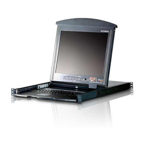
- Page 1 Hideaway™ LCD KVMP Switch KL3116 User Manual www.altusen.com...
-
Page 2: Fcc Information
This equipment has been tested and found to comply with the limits for a Class A digital device, pursuant to Part 15 of the FCC Rules. These limits are designed to provide reasonable protection against harmful interference when the equipment is operated in a commercial environment. -
Page 3: User Notice
`as is'. Should the programs prove defective following their purchase, the buyer (and not the manufacturer, its distributor, or its dealer), assumes the entire cost of all necessary servicing, repair and any incidental or consequential damages resulting from any defect in the software. -
Page 4: Safety Instructions
If an extension cord is used with this device make sure that the total of the ampere ratings of all products used on this cord does not exceed the extension cord ampere rating. - Page 5 Never push objects of any kind into or through cabinet slots. They may touch dangerous voltage points or short out parts resulting in a risk of fire or electrical shock.
-
Page 6: Rack Mounting
Before working on the rack, make sure that the stabilizers are secured to the rack, extended to the floor, and that the full weight of the rack rests on the floor. Install front and side stabilizers on a single rack or front stabilizers for joined multiple racks before working on the rack. -
Page 7: Package Contents
International Co., Ltd. © Manual Part No. PAPE-0262-1AXG Printing Date: 07/2006 Altusen and the Altusen logo are registered trademarks of ATEN International Co., Ltd. All rights reserved. All other brand names and trademarks are the registered property of their respective owners. -
Page 8: Table Of Contents
ALTUSEN Information ........xiii... - Page 9 Manual Port Switching ........28...
- Page 10 KL3116 User Manual Miscellaneous Actions ........52 Hotkey Summary Table .
-
Page 11: About This Manual
KL3116 User Manual About This Manual This User Manual is provided to help you get the most from your KL3116 system. It covers all aspects of installation, configuration and operation. An overview of the information found in the manual is provided below. - Page 12 Indicates text that you should key in. Monospaced Indicates keys you should press. For example, [Enter] means to press the Enter key. If keys need to be chorded, they appear together in the same bracket with a plus sign between them: [Ctrl+Alt].
-
Page 13: Altusen Information
Getting Help For additional help, advice, and information, ALTUSEN provides several support options. If you need to contact ALTUSEN technical support with a problem, please have the following information ready beforehand: Product model number, serial number, and date of purchase. -
Page 14: Product Information
KL3116 User Manual Product Information For information about all of ALTUSEN's products and how they can help you connect without limits, visit ALTUSEN on the web or contact an ALTUSEN Authorized Reseller. In the United States of America, call: 866-ALTUSEN (258-8736) -
Page 15: Chapter 1. Introduction
LCD monitor reclines flush against the rack to enable continuous monitoring of computers. An extra console port is provided on the rear panel to manage the LCD KVM switch from an external console (monitor, USB keyboard, and USB mouse) up to 20 meters away. -
Page 16: Features
(2) save all the space those extra components would take up; (3) save the space that a keyboard, monitor, and mouse would take with a standard KVM switch; (4) save on energy costs; and (5) eliminate the inconvenience and wasted effort involved in constantly moving from one computer to another. - Page 17 Supports Windows, Sun, Linux, Mac, Unix, Netware, AIX (RS6000), and DOS 6.2 and later Hideaway™ housing is slightly less than 1U with top and bottom clearance for smooth operation in 1U of rack space DDC emulation—video settings of each computer are automatically...
-
Page 18: System Requirements
@ 75Hz. Ensure that none of the computer resolution settings exceed the LCD monitor's maximum resolution. PS/2 mouse and keyboard ports (6-pin mini-DIN), or at least one USB port Cables Three custom cable sets are provided with this package: one console cable set for consoles with USB ports, one 2L-5702P KVM cable set for computers with PS/2 ports, and one 2L-5202U KVM cable set for computers with USB ports. -
Page 19: Operating Systems
Chapter 1. Introduction Operating Systems ® ® Microsoft Windows 95, 98, 98SE, ME, NT, 2000, XP or later ® Mac OS 8.6, 9.0, 9.1, X, 10.1, 10.2, 10.3 or later ® ® RED HAT Linux 6.0, 7.1, 7.2, 7.3, 8.0 or later Mandrake Linux 9.0 or later... -
Page 20: Kl3116 Front View
KL3116 Front View Component Description Upper Handle Pull to slide the LCD module out; push to slide the module in. See item 7 in this table and page 19 for more details on sliding the console in and out. LCD Module See LCD Module, page 8. -
Page 21: Keyboard Module
The Num Lock, Caps Lock, Scroll Lock LEDs are located Reset Switch here. A Reset Switch is located just to the right of the Lock LEDs. Press this recessed switch in with a thin object to perform a system reset. -
Page 22: Lcd Module
LCD Module Component Description LCD Display After sliding the LCD module out, flip up the cover to access the LCD monitor. LCD Controls Buttons to control the position and picture settings of the LCD display are located here. See page 26 for details. -
Page 23: Kl3116 Rear View
KL3116 Rear View Component Description Power Switch This is a standard rocker switch that powers the unit On and Off. Daisy Chain Port When daisy chaining units, the cable plugs in here. KVM Ports (CPU The cables that link to the computers plug in here. - Page 24 KL3116 User Manual This Page Intentionally Left Blank...
-
Page 25: Chapter 2. Installation
L Brackets Side Mountng Brackets Note: It takes two people to mount the switch: one to hold it in place, the other to screw it in. Optional mounting kits—including single person Easy Installation kits—are available with a separate purchase. See Optional Rack Mounting, page 66, for... - Page 26 Remove the packing material before installing the unit, as shown in the diagram below. 2. While one person positions the switch in the rack and holds it in place, the second person—using the screws provided with the rack mounting kit—...
- Page 27 4. After the L brackets have been secured, tighten the front bracket screws. Note: 1. Cage nuts are provided for racks that are not prethreaded. 2. Allow at least 5.1 cm on each side for proper ventilation, and at least 12.7 cm at the back for the power cord and cable clearance.
-
Page 28: Single Stage Installation
Single Stage Installation In a Single Stage installation, there are no additional switches daisy chained down from the first unit. To set up a single stage installation, refer to the installation diagrams beginning on page 15 (the numbers in the diagram correspond to the numbers of the installation steps) and do the following: 1. - Page 29 Chapter 2. Installation Single Stage Installation Diagram...
- Page 30 KL3116 User Manual USB Console Connection USB Cable Connection PS/2 Cable Connection...
-
Page 31: Daisy Chaining
To set up a daisy chained installation, refer to the daisy chain installation diagram on page 18 and do the following: 1. Make sure that power to all the devices you will be connecting up has been turned off. 2. Use a daisy chain cable set (described in the Cables section, page 4), to... - Page 32 KL3116 User Manual and ACS-1216A has an LED display on its front panel to indicate its Station ID (the Station ID for the First Stage unit (KL3116) is 01, the ID for the Second Stage unit (the first KH3116, KH0116, CS-1716, or ACS-1216A) is 02, the ID for the Third Stage unit is 03, etc.).
-
Page 33: Chapter 3. Basic Operation
As a safety precaution, to keep the console from accidentally sliding out, it is locked into the In position. Before you can pull it out, you must release it by pushing the catches on the unit's front panel toward the center of the switch. -
Page 34: Opening Separately
Opening Separately 1. Release the console by sliding the front panel catches toward the center and as you pull the top panel a few centimeters toward you. Once the con- sole has been released, you can let go of the catches. - Page 35 Chapter 3. Basic Operation 3. Rotate the top panel all the way back to expose the LCD screen. 4. Reach underneath and pull the keyboard module all the way out until it clicks into place.
-
Page 36: Opening Together
1. Release the console by sliding the front panel catches toward the center and as you pull the bottom panel a few centimeters toward you. Once the console has been released, you can let go of the catches. 2. Pull the bottom panel all the way out until it clicks into place. -
Page 37: Operating Precautions
Chapter 3. Basic Operation Operating Precautions The maximum load bearing capacity of the keyboard module is 30kg. Failure to heed the information below can result in damage to the keyboard module. RIGHT Rest your hands and arms lightly on the keyboard module as you work. -
Page 38: Closing The Console
KL3116 User Manual Closing the Console 1. Pull the release catches located on either side of the keyboard toward you to release the keyboard module, then slide the module slightly in. 2. Let go of the catches. Using the front handle, push the keyboard module... - Page 39 Chapter 3. Basic Operation 3. Rotate the LCD module all the way down, then pull the rear catches to release the LCD module. 4. Using the front handle, push the module all the way in.
-
Page 40: Lcd Osd Configuration
KL3116 User Manual LCD OSD Configuration The LCD Buttons The LCD OSD allows you to set up and configure the LCD display. Four buttons are used to perform the configuration, as described in the table below: Button Function MENU When you have not entered the LCD OSD Menu function, pressing this button invokes the Menu function and brings up the Main Menu. -
Page 41: The Adjustment Settings
Selects the language that the OSD displays its menus in. OSD Duration Lets you set the amount of time that the OSD displays on the screen. If there is no input for the amount of time you choose, the OSD display turns off. Reset Resets the menu and submenu adjustments (except for language settings) to the original factory default settings. -
Page 42: Port Selection
You can switch station positions by simply unplugging from the old parent and plugging into a new one. After you do, in order for the OSD menus to correspond to the change, you must reset the Station IDs in the OSD. See RESET STATION IDS, page 40, for details. -
Page 43: Powering Off And Restarting
Chapter 3. Basic Operation Powering Off and Restarting If it becomes necessary to Power Off one of the units, unplug its power cable from the rear panel. Before starting it back up you must do the following: 1. Shut down all the computers that are attached to it. -
Page 44: Port Id Numbering
Each KVM Port on a KL3116 installation is assigned a unique Port ID. The Port ID is made up of two parts: a Station Number, and a Port Number: The Station Number: is a two digit number which reflects the switch's position in the daisy chain sequence. -
Page 45: Chapter 4. Osd Operation
OSD Main Screen. If this is the first time that the OSD is being run, or if the password function has not been set, simply press [Enter]. The OSD Main Screen comes up in Administrator Mode. - Page 46 Administrator and can't be accessed by ordinary Users. 2. The OSD always starts in List view with the highlight bar at the same position it was in the last time it was closed. 3. Only the ports that have been set accessible by the Administrator for the currently logged in User are visible (see SET ACCESSIBLE PORTS page 40, for details).
-
Page 47: Osd Navigation
Main Screen, or press [F8]. To move up or down through the list one line at a time, Click the Up and Down Triangle symbols ( or use the Up and Down Arrow Keys. If there are more list entries than there is room for on the Main Screen, the screen will scroll. -
Page 48: Osd Functions
OSD functions are used to configure and control the OSD. For example, you can rapidly switch to any port, scan selected ports only, limit the list you wish to view, designate a port as a Quick View Port, create or edit a port name, or make OSD setting adjustments. -
Page 49: F2 List
Chapter 4. OSD Operation F2 LIST This function lets you broaden or narrow the scope of which ports the OSD displays (lists) on the Main Screen. Many of the OSD functions only operate on the computers currently selected for Listing on the Main Screen with this function. -
Page 50: F3 Set
POSITION anywhere on the screen. Use the Mouse or the Arrow Keys plus Pg Up, Pg Dn, Home, End, and 5 (on the numeric keypad with Num Lock off), to position the Port ID display, then Click or press [Enter] to lock the position and return to the Set submenu. - Page 51 Accessible and have been selected as Quick View Ports and are Powered On. The default is ALL. SCREEN If there is no input from the console for the amount of time set with this BLANKER function, the screen is blanked. Key in a value from 1–30 minutes, then press [Enter].
-
Page 52: F4 Adm
F4 is an Administrator only function. It allows the Administrator to configure and control the overall operation of the OSD. To change a setting Double Click it; or use the Up and Down Arrow Keys to move the highlight bar to it, then press [Enter]. - Page 53 This function allows the Administrator to create, modify, or delete port names. To Edit a port name: 1. Click the port you want, or use the Navigation Keys to move the highlight bar to it, then press [Enter].
- Page 54 QV column of the LIST on the Main Screen to indicate so. When a port is deselected, the arrowhead disappears. If one of the Quick View options is chosen for the LIST view (see F2 LIST, page 35), only a Port that has been selected here will display on the List.
- Page 55 Changes will not be saved until you logout. * If you are installing a Sun or Mac computer, before you run it for the first time you must set the correct operating system for the port it is connected to...
-
Page 56: F5 Skp
To skip from the current port to the last port of the previous station ↑ in the List. To skip from the current port to the first port of the next station in ↓ the List. Note: When you Skip, you only Skip to the previous or next available computer that is in the Scan/Skip Mode selection (see page 37). -
Page 57: F6 Brc
BRC works in conjunction with the F2 LIST function. The LIST function (see page 35), is used to broaden or narrow the focus of which Ports appear on the OSD Main Screen. When you Broadcast a command, it is to the Ports currently displayed on the OSD Main Screen. -
Page 58: F7 Scan
Auto Scan Mode. While you are in Auto Scan Mode, you can pause the scanning in order to keep the focus on a particular computer either by pressing P, or with a Left Click of the mouse. -
Page 59: F8 Lout
Chapter 4. OSD Operation F8 LOUT Clicking the F8 field, or pressing [F8], logs you out of the OSD and blanks the Console screen. This is different from simply deactivating the OSD when you are at the Main Screen by pressing [Esc]. - Page 60 KL3116 User Manual This Page Intentionally Left Blank...
-
Page 61: Chapter 5. Hotkey Operation
Note: There is an alternate invocation combination (see page 51 for details.) When HKM Is Active The Caps Lock and Scroll Lock LEDs flash in succession to indicate that HKM is in effect. They stop flashing when you exit HKM. -
Page 62: Hotkey Port Access
1. Invoke HKM (see page 47). 2. Key in the computer's Port ID number. The Port ID numbers display on the Command Line as you key them in. If you make a mistake, use [Backspace] to erase the wrong number. -
Page 63: Auto Scan Mode
You must exit Auto Scan Mode in order to regain normal control of the console. While you are in Auto Scan Mode, you can pause the scanning in order to keep the focus on a particular computer by pressing P, or with a left-click of the mouse. -
Page 64: Skip Mode
This feature allows you to switch between computers in order to monitor them manually. You can dwell on a particular port for as long or as little as you like—as opposed to Auto Scanning, which automatically switches after a fixed interval. -
Page 65: Hotkey Configuration
Chapter 5. Hotkey Operation Hotkey Configuration Alternate Hotkey Invocation Keys An alternate set of Hotkey Invocation keys is provided in case the default set conflicts with programs running on the computers. To switch to the alternate Hotkey Invocation set, do the following: 1. -
Page 66: Platform Setup
Note: The brackets indicate the keys you should press. Simply press the indicated keys—do not type the brackets. Miscellaneous Actions Hotkeys are also used to reset the USB, and toggle the beeper On and Off. To perform any of these operations, do the following: 1. Invoke HKM (see page 47) 2. -
Page 67: Hotkey Summary Table
[Num Lock] + [-] [H] or Changes the Hotkey Invocation keys from [Num [Ctrl] + [F12] [H] Lock] + [-] to [Ctrl] + [F12] and vice versa. [Num Lock] + [-] [T] or Changes the OSD Hotkey from [Scroll Lock] [Ctrl] + [F12] [T] [Scroll Lock] to [Ctrl] [Ctrl] and vice versa. - Page 68 KL3116 User Manual This Page Intentionally Left Blank...
-
Page 69: Chapter 6. Keyboard Emulation
Chapter 6 Keyboard Emulation Mac Keyboard The PC compatible (101/104 key) keyboard can emulate the functions of the Mac keyboard. The emulation mappings are listed in the table below. PC Keyboard Mac Keyboard [Shift] Shift [Ctrl] Ctrl [Ctrl] [1] [Ctrl] [2]... - Page 70 KL3116 User Manual Sun Keyboard The PC compatible (101/104 key) keyboard can emulate the functions of the Sun keyboard when the Control key [Ctrl] is used in conjunction with other keys. The corresponding functions are shown in the table below. PC Keyboard...
-
Page 71: Chapter 7. Firmware Upgrade
Before You Begin To prepare for the firmware upgrade, do the following: 1. From a computer that is not part of your KVM installation go to our Inter- net support site and choose the model name that relates to your device (KL3116) to get a list of available Firmware Upgrade Packages. - Page 72 Firmware Upgrade Port on the switch. 4. Shut down the computers on your KL3116 installation. 5. From your KVM switch console, bring up the OSD (see page 31) and select the F4 ADM function. 6. Scroll down to FIRMWARE UPGRADE (see page 41). Press [Enter], then press [Y] to invoke Firmware Upgrade Mode.
-
Page 73: Starting The Upgrade
To upgrade your firmware: 1. Run the downloaded Firmware Upgrade Package file, either by double- clicking the file icon, or by opening a command line and entering the full path to it. The Firmware Upgrade Utility Welcome screen appears: 2. Read and Agree to the License Agreement (enable the I Agree radio button). - Page 74 KL3116 User Manual 4. As you select a device in the list, its description appears in the Device Description panel. 5. Click Next to perform the upgrade. If you enabled Check Firmware Version, the Utility compares the device's firmware level with that of the upgrade files. If it finds that the device's...
-
Page 75: Upgrade Succeeded
Chapter 7. Firmware Upgrade Upgrade Succeeded After the upgrade has completed, a screen appears to inform you that the procedure was successful: Click Finish to close the Firmware Upgrade Utility. -
Page 76: Upgrade Failed
If the upgrade failed to complete successfully a dialog box appears asking if you want to retry. Click Yes to retry. If you Click No, the Upgrade Failed screen appears. Click Cancel to close the Firmware Upgrade Utility. See the next section, Firmware Upgrade Recovery, for how to proceed. -
Page 77: Appendix
Connection Table The following table indicates the relationship between the number of KH3116, KH0116, CS-1716, or ACS-1216A units that are cascaded from the KL3116 and the number of computers that they control on a daisy chained installation: Computers Computers Computers Computers 1–16... -
Page 78: Osd Factory Default Settings
Scan/Skip Mode Screen Blanker 0 (Disabled) Logout Timeout 0 (Disabled) Beeper Y (Activated) Accessible Ports F (Full Access) For all Users on all Ports Hotkey Command Mode Y (Activated) Set Operating System Keyboard Language Auto Set Console Mode 0: Dual-Console... -
Page 79: Clear Login Information
PLEASE POWER OFF THE SWITCH, REMOVE THE JUMPER, CLOSE THE CASE, THEN RESTART. 4. After you start back up, the OSD login function acts exactly the way it did the first time the switch was run (see page 31) and you can reset passwords... -
Page 80: Optional Rack Mounting
105 cm racks. – To install the long bracket standard rack mount kit, simply replace the short L brackets on the standard rack mount kit with the long ones, and mount the switch according to the instructions given on page 11. - Page 81 Remove the packing material before installing the unit, as shown in the diagram below. 3. Attach the left and right easy-installation mounting rails to the inside of the rack. The flange that supports the switch will be to the inside.
- Page 82 4. Slide the switch onto the support flanges. Use the screws supplied with this package to loosely attach the front of the switch to the front of the rack (only tighten the screws part way).
- Page 83 Phillips I head M4 x 6 6. Slide the switch open and closed a couple of times to be sure that it is properly aligned and operating smoothly. (See page 19 for opening and closing procedures.) 7. After determining that the switch is properly lined up and operating correctly, finish up by fully tightening down the partially tightened front attachment screws inserted in step 3.
-
Page 84: Dedicated Invocation Keys
KL3116 User Manual Dedicated Invocation Keys Two dedicated keys are provided on the keyboard module to make it easy to invoke Hotkey Mode and the OSD (as shown in the diagram below): Note: These keys are toggles. Press once to invoke the feature, press again to... -
Page 85: Specifications
Scan Interval 1–255 seconds Video 1280x1024@75Hz; DDC2B Environment Operating Temperature 0–40 Storage Temperature -20–60 Humidity 0–80% RH, Non-condensing Physical Housing Metal Properties Weight 17.5 kg Dimensions (L x W x H) 70.5 x 48.2 x 4.4 cm (19" / 1U) -
Page 86: Troubleshooting
The distance between the external console and the the external monitor. KL3116 is too great. The maximum VGA cable distance should not exceed 20m and, in some cases, may need to be shorter. Replace the VGA cable with one of an appropriately short length. -
Page 87: Sun Systems
1. Open a console and issue the following command: ffbconfig -res 1024x768x60 2. Log out. 3. Log in. * These solutions work for most common Sun VGA cards. If these procedures fail to resolve the problem, consult the manual for the Sun VGA card. -
Page 88: Limited Warranty
When returning the product, you must ship the product in its original packaging or packaging that gives an equal degree of protection. Include your proof of purchase in the packaging and the RMA number clearly marked on the outside of the package. -
Page 89: Index
ALTUSEN Information, xiii Installation, 11 Daisy Chaining, 17 Single Stage, 14 Basic Operation, 19 Introduction, 1 Cables, 4 Keyboard Emulation Clear Login Information, 65 Mac, 55 Closing the Console, 24 Sun, 56 Connection Table, 63 KL3116 Console Computer Connection Table, 63... - Page 90 KL3116 User Manual Powering Off and Restarting, 29 Specifications, 71 Station IDs, 17 Station Positions Rack mounting Switching, 28 Optional, 66 Switching Station Positions, 28 Standard, 11 System Requirements, 4 Rear View, 9 Restarting, 29 Troubleshooting, 72 Safety Instructions General, iv...
Need help?
Do you have a question about the Altusen KL3116M and is the answer not in the manual?
Questions and answers