Table of Contents
Advertisement
Quick Links
Advertisement
Table of Contents

Related Manuals for Altusen PN9108U


Summary of Contents for Altusen PN9108U
- Page 1 Power over the NET PN9108U User Manual www.altusen.com 2005-09-07...
-
Page 2: Regulatory Information
PN9108U User Manual Regulatory Information 1. This is an FCC Class A product. In a domestic environment this product may cause radio interference in which case the user may be required to take adequate measures. This equipment has been tested and found to comply with the limits for a Class A digital device, pursuant to Part 15 of the FCC Rules. -
Page 3: User Notice
PN9108U User Manual User Notice All information, documentation, and specifications contained in this manual are subject to change without prior notification by the manufacturer. The manufacturer makes no representations or warranties, either expressed or implied, with respect to the contents hereof and specifically disclaims any warranties as to merchantability or fitness for any particular purpose. -
Page 4: Safety Instructions
PN9108U User Manual Safety Instructions General M Read all of these instructions. Save them for future reference. M Follow all warnings and instructions marked on the device. M Do not place the device on any unstable surface (cart, stand, table, etc.). If the device falls, serious damage will result. - Page 5 M The device does not operate normally when the operating instructions are followed. M Only adjust those controls that are covered in the operating instructions. Improper adjustment of other controls may result in damage that will require extensive work by a qualified technician to repair. PN9108U User Manual 2005-09-07...
-
Page 6: Rack Mounting
PN9108U User Manual Rack Mounting M Before working on the rack, make sure that the stabilizers are secured to the rack, extended to the floor, and that the full weight of the rack rests on the floor. Install front and side stabilizers on a single rack or front stabilizers for joined multiple racks before working on the rack. -
Page 7: Power Cords
PN9108U User Manual Power Cords Use the cables supplied with this package. If it becomes necessary to replace the cables supplied with this package, be sure to use cables of at least the same standard as the ones provided. Power Cord:... -
Page 8: Package Contents
PN9108U installation. * Features may have been added to the PN9108U since this manual was written. Please visit our website to download the latest version of this manual. -
Page 9: Table Of Contents
Logging In ....... . 15 The PN9108U Main Screen ..... 16 Device Selector . - Page 10 PN9108U User Manual Chapter 4 Administration Working Environment Configuration ....21 General ....... 21 Network .
-
Page 11: About This Manual
PN9108U User Manual About This Manual This User Manual is provided to help you get the most from your PN9108U system. It covers all aspects of installation, configuration and operation. An overview of the information found in the manual is provided below. -
Page 12: Conventions
PN9108U User Manual Conventions This manual uses the following conventions: Indicates text that you should key in. Courier Indicates keys you should press. For example, [Enter] means to press the Enter key. If keys need to be chorded, they appear together in the same bracket with a plus sign between them: [Ctrl+Alt]. -
Page 13: Product Information
M In the United States of America, call: 866-ALTUSEN (258-8736) M In Canada and South America, call: 949-453-8885 M In all other locations, call: 886-2-8692-6789 M Visit ALTUSEN on the web at http://www.altusen.com for a list of locations and telephone numbers PN9108U User Manual xiii 2005-09-07... - Page 14 PN9108U User Manual Notes: 2005-09-07...
-
Page 15: Introduction
Chapter 1. Introduction Overview The PN9108U Power over the NET™ is a control unit that provides remote power management for eight AC outlets via a TCP/IP connection, allowing administrators to control the power off, power on, and reboot status for each attached device from any computer connected to the Internet, whether down the hall, or half way around the world. -
Page 16: Features
PN9108U User Manual Features M Remote power on/off/reboot control for eight outlets via TCP/IP and a built in 10/100 Ethernet port M Daisy chain up to 15 additional stations to control up to 128 outlets M Manual switching between Local and Remote access for each port via... -
Page 17: Optional Capability
M Out of Band Connectivity - OOB power on/off/reboot control of the computers attached to the PN9108U: M Local control via a direct terminal link from the PN9108U’s RS-232 port to the computer’s RS-232 port M Remote control via an external modem for either a console terminal connection, or for an ISP internet connection. -
Page 18: Requirements
PN9108U User Manual Requirements M Browsers accessing the PN9108U must support SSL 128 bit encryption. M For cold booting of attached computers, the computer’s BIOS must support this feature. M For Safe Shutdown: M The computer must be running Windows (Windows 98 or higher). -
Page 19: Hardware Setup
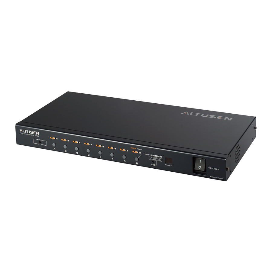
Hardware Setup Front View 1. Port LEDs The Port LEDs provide status information about their corresponding AC outlet ports. There is one pair of LEDs for each port. The one on the left is the Remote Access LED; the one on the right is the Power LED: M A Remote Access LED lights GREEN to indicate that the device attached to its corresponding port is capable of being controlled remotely. - Page 20 PN9108U User Manual 3. Station ID LED M The PN9108U’s Station ID usually displays here. If this is a Single Station installation (see p. 12), or the First Station on a Daisy Chained installation (see p. 14), the PN9108U has a Station ID of 01.
-
Page 21: Rear View
Rear View 1. Power Socket The power cable from the AC source plugs in here. 2. Circuit Breaker Press to reset the circuit. 3. AC Power Outlets The power cables that connect to the computers plug in here. 4. RS-232 Port This port can be used to attach a UPS for safe shutdown of the computers configured for Safe Shutdown should there be a power outage. - Page 22 Provides safe shutdown and rebooting for Windows 98SE, ME, NT, 2000, XP and 2003 Server systems. 6. PON (Power over the NET™ ™ ) Output Port When daisy chaining PN9108U Stations, this is the Chain Out port. See p. 14 for daisy chaining details. 7. Power Switch This standard rocker switch powers the PN9108U On and Off.
-
Page 23: Installation
PN9108 is plugged into. Stacking The PN9108U can be placed on any appropriate level surface that can safely support its weight plus the weight of its attached cables. To place or stack the PN9108U, remove the backing material from the bottom of the rubber feet that came with this package, and stick them onto the switch’s bottom panel at... -
Page 24: Rack Mounting
PN9108U User Manual Rack Mounting The PN9108U can be installed in most standard 19" (1U) racks. To rack mount the unit do the following: 1. Separate the front and rear modules by removing the four module attaching screws: Phillips hex head M3 x 8 2. - Page 25 Chapter 2 - Hardware Setup 3. Position the device in the rack and align the holes in the mounting brackets with the hole in the rack. 4. Screw the mounting brackets to the rack. Note: Cage nuts are provided for racks that are not prethreaded. 2005-09-07...
-
Page 26: Single Stage Installation
PN9108U User Manual Single Stage Installation In a Single Stage installation, there are no additional PN9108U Stations daisy chained down from the first unit. To set up a single stage installation, refer to the installation diagram below (the numbers in the diagram correspond to the numbered steps), and do the following: 1. - Page 27 5. Use the AC power cord provided with this package to connect the PN9108U’s Power Socket to an AC power source. Note: We strongly advise that you do not plug the PN9108U into a multi socket extension cord, since it may not receive enough amperage to operate correctly.
-
Page 28: Daisy Chaining
To set up a daisy chained installation do the following: 1. For each PN9108U Station that you add to the chain, use the DB-9 to DB-9 PON cable that was provided with it to connect the parent PN9108U’s PON OUT port to the child PN9108U’s PON IN port. -
Page 29: Browser Operation
Note: Browsers accessing the PN9108U must support SSL 128 bit encryption. 1. Open your browser and specify the IP address of the PN9108U you want to access in the browser’s URL location bar. Note: 1. Get the IP address from the PN9108U administrator 2. -
Page 30: The Pn9108U Main Screen
PN9108U User Manual The PN9108U Main Screen After you have successfully logged in, the PN9108U Main Screen appears: M The icons arranged horizontally across the top are used by the administrator to configure the PN9108U’s working environment. Administrative functions are explained in Chapter 4. -
Page 31: Device Selector
Station you want to work with. When you select a Station, its Power Status screen appears. Note: 1. Each PN9108U’s Station ID is displayed in the Station ID LED on its front panel (see p. 6). 2. The outlets in the Power Status panels are for the Station currently selected in the Device Selector. -
Page 32: The Power Status Screen
Power Buttons: The top panel of the Power Status screen is divided into eight subareas which correspond to the A- H outlets on the PN9108U’s rear panel. Each subarea is composed of a socket icon that functions as the Power Button for its corresponding outlet, and an information panel to its right. - Page 33 The Information Panel: The information panel shows the Outlet’s name and currently selected power option. These parameters are set by the Administrator with the Configuration function (see p. 27 for details). Reboot: If Reboot is enabled (by putting a check in the checkbox), the computer attached to the Outlet’s corresponding port will reboot instead of shutting off when the Power Button is clicked to turn the outlet off.
-
Page 34: The Bottom Panel
PN9108U User Manual The Bottom Panel The bottom panel allows you to control the power status of your outlet groups. Outlets can be placed into groups so that Power On/Off actions can be carried out on the entire outlet group at the same time, rather than performing the same action on each outlet individually. -
Page 35: Administration
Administration Working Environment Configuration The icon bar at the top of the main screen is used by the administrator to configure the PN9108U’s working environment. An explanation of each of the configuration functions is given in the sections that follow. - Page 36 System Information: The System Information section allows you to provide a name and description for the PN9108U installation. Providing a name and description is optional, but makes it convenient for system operators to distinguish among installation groups in large, installations when there are several groups of daisy chained PN9108Us.
-
Page 37: Network
Network Settings allows you to choose how the PN9108U obtains its IP address: Fixed IP Address: The default is for a fixed IP address. To give the PN9108U a fixed IP address, fill in the Network Settings and DNS Settings fields with values appropriate to the network you are on. - Page 38 Settings section are disabled, and a Mail Configuration panel appears: You can use these Mail Configuration fields to ascertain the IP address that was dynamically assigned to the PN9108U by doing the following: 1. Key in the domain name or IP address of the SMTP mail server for your network in the top field.
-
Page 39: Date / Time
When you click the Date / Time icon, the following dialog box appears: The date and time settings that the PN9108U is currently set to appear in the upper section. The large lower section offers three methods to set a new system... -
Page 40: Firmware
Click the Logout icon to end your PN9108U session. Note: It is important to log out when you end your session. Otherwise, you must wait until the timeout setting has expired before the PN9108U can be accessed again. (See Connection Control under the General Settings dialog information, p. -
Page 41: Power Management Configuration
Chapter 4 - Administration Power Management Configuration The buttons in the Device Control panel allow the PN9108U administrator to configure the power management functions of each of the PN9108U Stations on the installation. The functions provided by each of the buttons are explained in the sections that follow. - Page 42 Safe Shutdown on the computer attached to its Outlet. When the Power Button is clicked ON, the PN9108U waits for the amount time set in the Power On Delay field (see below), and then restarts the computer. The front panel LEDs flash while the action is pending.
- Page 43 Heading Kill the Power If this option is selected, the PN9108U waits for the amount time set in the Power Off Delay field (see below), and then turns the Outlet’s power OFF when its Power Button is clicked to turn off the power. Turning the power off performs a cold (non-safe) shutdown.
- Page 44 The maximum number of characters for the name is 15. UPS: M The PN9108U provides simple signal UPS support. If you connect a UPS to the PN9108U’s RS-232 port, and enable the UPS function, should the main power be interrupted and the UPS kick in, the PN9108U can initiate a safe shutdown for all of the computers that have been cabled and configured for a safe shutdown.
- Page 45 M It is also possible to attach an individual UPS for each computer to the PN9108U’s outlet ports. In this case: M Do not enable the PN9108U’s UPS function - since that function only works with a UPS device attached to its RS-232 port.
-
Page 46: Schedule
PN9108U User Manual Schedule Clicking the Device Control Schedule button brings up the Scheduling dialog box: This dialog box allows you to set up a scheduled Power On/Off configuration for each of the outlets. To do so: 1. Select your outlet from the buttons in the upper panel. -
Page 47: User Management
Management dialog box: This dialog box allows the Administrator to set up Usernames and Passwords that operators must provide in order to log into the PN9108U. The minimum number of characters for each field is 4; the maximum is 15. -
Page 48: Monitor
On/Off status of each outlet. Note: If the No timeout on monitoring function is enabled in the General Settings dialog box (see p. 21), the PN9108U will not time out when this function is being used. -
Page 49: Log
Clicking the Device Control Log button brings up the Event Log dialog box: The PN9108U maintains a log file of the last 2048 events that took place on it. This dialog box allows you to select the range of events you wish to view: M Choose Today then click OK to see a listing of only today’s events. - Page 50 PN9108U User Manual Once you make a choice and click OK an Event Log List, similar to the one below, appears: When you have finished viewing the event list: M If you want to return to the Event Log dialog box, click Back.
-
Page 51: Safe Shutdown And Reboot
In order to use this function: M You must connect a Safe Shutdown Cable from the PN9108U to the computer (see Single Stage Installation, p. 12). -
Page 52: Automated Setup
PN9108U User Manual 4. The wording for the System after AC back function may vary somewhat from system to system. For example: AC Loss Auto Restart Restore on AC Power Loss In the BIOS settings, choose Power On (Full On). -
Page 53: Uninstalling
By default, PMonitor monitors the COM1 port. If the utility displays an error message stating that it is unable to open the COM1 port, it means that the port is already being used by another utility. You can either stop the other utility, and try again, or use a different COM port for the PMonitor program. -
Page 54: Manual Setup
PN9108U User Manual Manual Setup Windows NT, 2000, XP, and Server 2003 can be manually configured for safe shutdown and rebooting instead of using the Power Monitor utility. The following sections explain the procedures involved. Windows 2000 / XP / Server 2003:... - Page 55 2. Click Next. A dialog box similar to the one below appears: Select the options in the dialog box so that they match the settings shown in the figure above. 3. Click Finish; click OK. To check that the setup is working: 1.
- Page 56 PN9108U User Manual 1. Go to the Control Panel; open the UPS entry. A dialog box similar to the one below appears: a. For the COM port entry, select the COM port on the computer that the Safe Shutdown Cable is plugged into.
-
Page 57: Upgrading The Firmware
Preparation 1. From your computer, go to our Internet support site and choose the model name that relates to your device (PN9108U) to get a list of available Firmware Upgrade Packages. 2. Choose the Firmware Upgrade Package you want to install (usually the most recent), and download it to your computer. -
Page 58: Starting The Upgrade
2. If you enable Check Firmware Version, the upgrade function compares the device’s firmware level with that of the upgrade files. If it finds that the PN9108U’s current version is equal to, higher than, the upgrade version, it won’t overwrite the PN9108U’s version. -
Page 59: Appendix
If you are an administrator logging in for the first time, you need to access the PN9108U in order to give it an IP address that users can connect to. M If your computer is on the same network segment as the PN9108U, you can simply specify the switch’s default IP address (192.168.0.60) in your... - Page 60 2. Specify the switch’s default IP address (192.168.0.60) in your browser, and you will be able to connect. 3. Assign a fixed IP address for the PN9108U that is suitable for the network segment that it resides on. 4. After you log out, be sure to reset your computer’s IP address to its original value.
- Page 61 Where the IP address that you assign is one suitable for the network segment that the PN9108U resides on. Note: The PN9108U’s MAC address can be found on its bottom panel. 3. Turn the power to the PN9108U back on.
-
Page 62: Troubleshooting
PN9108U User Manual Troubleshooting Problem 1: On a safe shutdown and reboot operation, when rebooting, the computer stops at the logon screen and waits for a Username and Password instead of automatically logging on. Solution: The Autologon function hasn’t been configured for the computer. Set it up as follows: 1. - Page 63 Appendix Problem 2: The computer has an older mainboard that doesn’t support APM in the BIOS. What can I do to get Safe Shutdown and Reboot working? Solution: If you are running Windows 2000, XP, or Server 2003, you can do the following: 1.
- Page 64 PN9108U User Manual Problem 3: I have enabled Synchronize with NTP Server in the Date / Time dialog box, but I am unable to obtain the date and time from an NTP server on the internet. Solution: Contact your MIS department and have them enable a port for the NTP server.
-
Page 65: Administrator Login Failure
4. When the Link and 10/100Mbps LEDs flash, power off the switch. 5. Remove the jumper cap from J6. 6. Close the housing and start the PN9108U back up. After you start back up, you can use the default Username and Password (see p. -
Page 66: Specifications
PN9108U User Manual Specifications Function Power Inlet 1 x IEC 60320/C14 (M) Power Outlets 8 x IEC 60320/C13 (F) I/P Rating (Total input) 100 ~ 120 V AC; 50/60Hz; 12A (max) O/P Rating Per port 100 ~ 120 V AC; 50/60Hz; 9A (max) Total 100 ~ 120 V AC;... -
Page 67: Battery Replacement
Appendix Battery Replacement This equipment is provided with a replaceable lithium battery: CR2032 3V. Replacement by an incorrect type may result in an explosion. CAUTION! RISK OF EXPLOSION IF BATTERY IS REPLACED BY AN INCORRECT TYPE. DISPOSE OF USED BATTERIES ACCORDING TO THE INSTRUCTIONS. -
Page 68: Limited Warranty
PN9108U User Manual Limited Warranty ALTUSEN warrants this product against defects in material or workmanship for a period of one (1) year from the date of purchase. If this product proves to be defective, contact ALTUSEN’s support department for repair or replacement of your unit. ALTUSEN will not issue a refund. Return requests can not be processed without the original proof of purchase. -
Page 69: Index
Overview ..... 1 PN9108U Front view ....5 Rear view . - Page 70 PN9108U User Manual Power status screen Bottom panel ....20 Top panel ....18 Rack mounting .
Need help?
Do you have a question about the PN9108U and is the answer not in the manual?
Questions and answers