Invacare Electric Portable Patient Lift RPA600-1E Operating & Maintenance Manual
Electric portable
Hide thumbs
Also See for Electric Portable Patient Lift RPA600-1E:
Table of Contents
Advertisement
Quick Links
Owner's Operator and Maintenance Manual
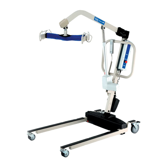
Electric Portable
Patient Lift - RPA600-1E
DEALER: This manual MUST be given to
the user of the patient lift.
USER: BEFORE using this patient lift, read
this manual and save for future reference.
For more information regarding
Invacare products, parts, and services,
please visit www.invacare.com
Advertisement
Table of Contents
Troubleshooting

Related Manuals for Invacare Electric Portable Patient Lift RPA600-1E


Summary of Contents for Invacare Electric Portable Patient Lift RPA600-1E
- Page 1 Patient Lift - RPA600-1E DEALER: This manual MUST be given to the user of the patient lift. USER: BEFORE using this patient lift, read this manual and save for future reference. For more information regarding Invacare products, parts, and services, please visit www.invacare.com...
-
Page 2: Symbol Legend
ATTEMPTING TO USE THIS EQUIPMENT - OTHERWISE, INJURY OR DAMAGE MAY OCCUR. Invacare products are specifically designed and manufactured for use in conjunction with Invacare accessories. Accessories designed by other manufacturers have not been tested by Invacare and are not recommended for use with Invacare products. -
Page 3: Table Of Contents
TABLE OF CONTENTS SYMBOL LEGEND ... 2 SPECIAL NOTES ... 5 LABEL LOCATION ... 6 PRODUCT PARAMETERS ... 7 Patient Lift RPA600-1E ...7 Reliant Scale RLS6 ...7 SECTION 1—GENERAL GUIDELINES ... 8 Weight Limitation...8 Assembling the Lift ...8 Using the Sling ...8 Operating the Lift ...9 Lifting the Patient...9 Transferring the Patient ...10... - Page 4 TABLE OF CONTENTS SECTION 4—LIFTING THE PATIENT ... 19 Preparing the Lift for Use ...19 Positioning the Lift ...19 Attaching a Sling to the Swivel Bar ...20 Lifting/Moving the Patient ...20 SECTION 5—TRANSFERRING THE PATIENT ... 22 Introduction ...22 Transferring to a Commode Chair ...23 Transferring to a Standard Commode ...24 Transferring to a Wheelchair ...24 SECTION 6—...
-
Page 5: Special Notes
SPECIAL NOTES Signal words are used in this manual and apply to hazards or unsafe practices which could result in personal injury or property damage. Refer to the table below for definitions of the signal words. SIGNAL WORD Danger indicates an imminently hazardous situation which, if not avoided, will result in DANGER death or serious injury. Warning indicates a potentially hazardous situation which, if not avoided, could result in WARNING death or serious injury. Caution indicates a potentially hazardous situation which, if not avoided, may result in CAUTION property damage or minor injury or both. -
Page 6: Label Location
LABEL LOCATION LABEL LOCATION Mast pivot MUST be tight to ensure safe use of your patient lift. Bolt MUST be checked at least every six (6) months in conjunction with periodic maintenance. See Owner's Manual. P/N 1130200 Rev. B Electric Portable Patient Lift - RPA600-1E Part No 1078988... -
Page 7: Product Parameters
PRODUCT PARAMETERS Patient Lift RPA600-1E Height at Sling Hook-up - MAX.: Height at Sling Hook-up - MIN.: Base Width OPEN: Base Width CLOSED: Base Height (Clearance): Base Length: Caster Size (FRONT/REAR): Weight Capacity: Weight Out of Carton: Battery: Charger Input: Charger Output/Charging Time: Audio Low Battery Alarm: Motor Safety Devices:... -
Page 8: Section 1-General Guidelines
SECTION 1—GENERAL GUIDELINES SECTION 1—GENERAL GUIDELINES WARNING SECTION 1 - GENERAL GUIDELINES contains important information for the safe operation and use of this product. Check all parts for shipping damage before using. In case of damage, DO NOT use the equipment. Contact the Dealer for further instructions. The Invacare patient lift is NOT a transport device. It is intended to transfer an individual from one resting surface to another (such as a bed to a wheelchair). Moving a person suspended in a sling over ANY distance is NOT recommended. DO NOT attempt any transfer without approval of the patient’s physician, nurse or medical assistant. Thoroughly read the instructions in this Owner’s Manual, observe a trained team of experts perform the lifting procedures and then perform the entire lift procedure several times with proper supervision and a capable individual acting as a patient. Invacare Stand Assist and Transfer slings are specifically designed to be used in conjunction with Invacare patient lifts. Slings and accessories designed by other manufacturers are not to be utilized as a component of Invacare’s patient lift system. Use of these products is prohibited and will void the lift’s warranty. Use the sling that is recommended by the individual’s doctor, nurse or medical assistant for the comfort and safety of the individual that is being lifted. -
Page 9: Operating The Lift
SECTION 1—GENERAL GUIDELINES Stand Assist Slings: Before lifting the patient, make sure the bottom edge of the stand assist sling is positioned on the lower back of the patient and the patient’s arms are outside the stand assist sling. Stand Assist Slings: The belt MUST be snug, but comfortable on the patient, otherwise the patient can slide out of the sling during transfer, possibly causing injury. Transfer Slings: Before lifting the patient, make sure the bottom edge of the transfer sling is at the base of the spine and the patient’s arms are outside the transfer sling. Transfer Slings: DO NOT raise the patient to a full standing position while using the transfer sling, otherwise injury may occur. DO NOT use any kind of plastic back incontinence pad or seating cushion between patient and sling material that may cause the patient to slide out of the sling during transfer. After each laundering (in accordance with instructions on the sling), inspect sling(s) for wear, tears, and loose stitching. Bleached, torn, cut, frayed, or broken slings are unsafe and could result in injury. Discard immediately. DO NOT alter slings. Be sure to check the sling attachments each time the sling is removed and replaced, to ensure that it is properly attached before the patient is removed from a stationary object (bed, chair or commode). If the patient is in a wheelchair, secure the wheel locks in place to prevent the chair from moving forwards or backwards. When connecting slings equipped with color coded straps to the patient lift, the shortest of the straps MUST be at the back of patient for support. Using long section will leave little or no support for patientʹs back. The loops of the sling are color coded and can be used to place patient in various positions. The colors make it easy to connect both sides of the sling equally. Make sure that there is sufficient head support when lifting a patient. Operating the Lift Make sure there is an audible click when mounting battery on the battery charger to confirm proper mounting. Otherwise, injury or damage may occur. Use the handles to push or pull the patient lift. Lifting the Patient Before positioning the legs of the stand up lift around the patient, make sure that the patient’s feet are out of the way of the foot plate, otherwise injury may occur. -
Page 10: Transferring The Patient
SECTION 1—GENERAL GUIDELINES Before lifting a patient from a stationary object (wheelchair, commode or bed), slightly raise the patient off the stationary object and check that all sling attachments are secure. If any attachment is not correct, lower the patient and correct the problem, then raise the patient and check again. During transfer, with the patient suspended in a sling attached to the lift, DO NOT roll caster base over objects such as carpet, raised carpet bindings, door frames, or any uneven surfaces or obstacles that would create an imbalance of the patient lift and could cause the patient lift to tip over. Use steering handle on the mast at ALL times to push or pull the patient lift. Invacare recommends locking the rear swivel casters ONLY when positioning or removing the sling (stand assist or transfer) from around the patient. Invacare does NOT recommend locking of the rear casters of the patient lift when lifting an individual. Doing so could cause the lift to tip and endanger the patient and assistants. Invacare DOES recommend that the rear casters be left unlocked during lifting procedures to allow the patient lift to stabilize itself when the patient is initially lifted from a chair, bed or any stationary object. Transferring the Patient Before transferring, check that the product’s weight capacity can withstand the patientʹs weight. Wheelchair wheel locks MUST be in a locked position before lowering the patient into the wheelchair for transport. Performing Maintenance Regular maintenance of patient lifts and accessories is necessary to assure proper operation. After the first 12 months of operation, inspect all pivot points and fasteners for wear. If the metal is worn, the parts MUST be replaced. Perform this inspection every six months thereafter. DO NOT overtighten mounting hardware. This will damage mounting brackets. Casters and axle bolts require inspections every six months to check for tightness and wear. Electric Portable Patient Lift - RPA6001E Part No 1078988... -
Page 11: Section 2-Assembly
SECTION 2—ASSEMBLY Assembling the Patient Lift Assembling the Mast to the Base NOTE: The mast assembly may be removed from the base for storage or transporting. The mast assembly MUST be properly secured to the base assembly before use. NOTE: For this procedure, refer to FIGURE 2.1. 1. Put the base on a level surface so all casters make contact with the floor. 2. Lock the rear casters (Detail “A”). 3. Remove the shoulder bolt, nut and washer, that secures the mast to the base. 4. Put the mast into the U‐shaped cut‐out in the base. 5. While supporting the mast, insert the shoulder bolt through the base, mast and washers. 6. Secure the mast in place with a nut. Part No 1078988 DETAIL “A” - LOCKING/UNLOCKING REAR CASTERS Step Here Step Here to... -
Page 12: Assembling The Electric Actuator To The Boom
Assembling the Electric Actuator to the Boom NOTE: For this procedure, refer to FIGURE 2.2. 1. Remove the shoulder bolt, washer and nut from the mounting bracket on the boom assembly. 2. Unpack the pinch guard from the patient lift carton. NOTE: The bottom of the electric actuator assembly will already be assembled to the mast mounting bracket. 3. Cut the plastic‐wrap that secures the boom and mast together. 4. Lift‐up on the boom and place it on your left shoulder. 5. Let the actuator rest on your right‐side of your chest and rotate the shaft extension of the actuator assembly until it lines‐up with the mounting holes in the boom assembly. 6. Place the pinch guard over the shaft extension of the actuator. 7. Align the holes of the boom assembly mounting bracket with those of the actuator and insert the bolt. Secure with nut. NOTE: Be sure that the bolt is completely through the holes of the boom assembly mounting bracket and the actuator assembly. The boom assembly will pivot easily if the mounting hardware is aligned properly when the boom assembly is secured to the mast. DO NOT overtighten the nut and bolt. This damages the mounting bracket. 8. -
Page 13: Installing The Shifter Handle
Installing the Shifter Handle NOTE: For this procedure, refer to FIGURE 2.3. 1. Line‐up the shifter handle threads with threaded opening in the base. 2. Turn the shifter handle clockwise and securely tighten into the base. Attaching the Battery Charger Mounting Bracket to the Wall NOTE: For this procedure, refer to FIGURE 2.4. 1. Place the battery charger mounting bracket on the wall at the desired position. 2. With a pencil, mark the middle hole position. 3. Measure down 6½ inches from the pencil mark and drill one mounting hole. 4. Install the bottom mounting screw until there is an approximate 1/8‐inch gap between the screw head and the wall. 5. Put the battery charger mounting bracket onto the bottom mounting screw. 6. Drill the other two mounting holes. 7. Screw the mounting screws through the battery charger mounting bracket and into the wall. Tighten securely. Make sure there is an audible click when mounting battery on the battery charger to confirm proper mounting. -
Page 14: Section 3-Operation
When the legs of the patient lift are no longer under the bed, return the legs to the maximum open position. NOTE: Invacare recommends that two assistants be used for all lifting preparation and transferring to/ from procedures; however, the patient lift can be operated by one assistant. The use of the patient lift by one assistant should be based on the evaluation of the health care professional for each individual case. - Page 15 SECTION 3—OPERATION DETAIL “A” - DETAIL “B” - HAND CONTROL DETAILS LOCKING/UNLOCKING REAR CASTERS Up Button Down Button Step Here Step Here to to Lock Unlock Hand Control Locking Caster Lever DETAIL “C” - EMERGENCY STOP Emergency Button Push in to stop, turn clockwise to reset.
-
Page 16: Closing/Opening The Legs
Closing/Opening the Legs NOTE: For this procedure, refer to FIGURE 3.2. If the shifter handle is NOT positioned completely into its mounting slot, DO NOT use the patient lift until the shifter handle is properly seated and the legs of the patient lift are locked in place. Otherwise, injury and/or damage may occur. The legs of the lift must be in the maximum open position and the shifter handle locked in place for optimum stability and safety. -
Page 17: Activating A Mechanical Emergency Release
SECTION 3—OPERATION Activating a Mechanical Emergency Release Primary Emergency Release NOTE: For this procedure, refer to FIGURE 3.3. NOTE: This procedure will bring the boom down or lift it up if the hand control is not functioning properly. To activate the primary emergency release, insert a pen into the hole labeled Emergency Up or Emergency Down on the control box. Control Emergency Release Hole FIGURE 3.3 Primary Emergency Release Secondary Emergency Release NOTE: For this procedure, refer to FIGURE 3.4. NOTE: All patient lift actuators are equipped with a mechanical emergency release. The mechanical release will enable the actuator to retract without power. NOTE: Use the primary emergency release first before using the secondary emergency release procedure. This procedure should only be used if the primary emergency release procedure is not functioning or is unreachable. NOTE: The lift MUST be under a load for the mechanical release to function. To activate the secondary release, pull up on the EMERGENCY ring and push down on the boom at the same time. Push DOWN on Boom Pull UP on EMERGENCY... -
Page 18: Charging The Battery
Charging the Battery NOTE: For this procedure, refer to FIGURE 3.5. NOTE: Invacare recommends the battery be recharged daily to prolong battery life. NOTE: An audible alarm will sound when battery is low. 1. Lift up on the handle on the back of the battery. 2. Lift the battery up and away from the control box. Make sure there is an audible click when mounting battery on the battery charger to ensure proper mounting. Otherwise, injury or damage may occur. 3. Place the battery on the battery charger. Push the top of the battery against the mounting bracket until there is an audible click. NOTE: The charge LED will illuminate. When charged, the LED will stop illuminating. NOTE: It will take approximately four hours to charge a battery that requires a full charge. -
Page 19: Section 4-Lifting The Patient
SECTION 4—LIFTING THE PATIENT SECTION 4—LIFTING THE PATIENT Preparing the Lift for Use NOTE: Although Invacare recommends that two assistants be used for all lifting preparation, transferring from and transferring to procedures, our equipment will permit proper operation by one assistant. The use of one assistant is based on the evaluation of the health care professional for each individual case. Positioning the Lift NOTE: For this procedure, refer to FIGURE 4.1. NOTE: Refer to General Guidelines on page 9 in this manual before proceeding further and observe all warnings indicated. NOTE: Before positioning the legs of the patient lift under a bed, make sure that the area is clear of any obstructions. WARNING The legs of the lift must be in the maximum open position and the shifter handle locked in place for optimum stability and safety. -
Page 20: Attaching A Sling To The Swivel Bar
Bleached, torn, cut, frayed or broken slings are unsafe and could result in injury. Discard IMMEDIATELY. DO NOT alter slings in any way. Invacare slings are made specifically for use with Invacare Patient Lifts. For the safety of the patient, DO NOT use slings and patient lifts of different manufacturers. - Page 21 NOTE: For this procedure, refer to FIGURE 4.2. NOTE: When the patient is lifted from the bed or the floor (with the patient’s head supported by the sling and/or an assistant), he/she will be raised to a sitting position (Detail “A” of FIGURE 4.2). 1. Press the up button on the hand control to raise the patient high enough to clear the bed surface. The patient’s full body weight will be supported by the lift. NOTE: The boom will stay in this position until the up or down buttons are pushed on the hand control. 2. Place the patient’s arms inside of the sling. 3. When the patient is clear of the bed surface, swing their feet off the bed (Detail “B” of FIGURE 4.2). 4. Using the handle, move the patient lift away from the bed. 5. Turn the patient so that he/she faces assistant operating the patient lift (Detail “C” of FIGURE 4.2). 6. Press the down button to lower the patient so that his/her feet rest on the base of the lift, straddling the mast. NOTE: The lower center of gravity provides stability making the patient feel more secure and the lift easier to move. 7. Push the lift with both hands firmly on the steering handle. DETAIL “A” - LIFTING THE PATIENT DETAIL “B” - MOVING THE PATIENT DETAIL “C”...
-
Page 22: Section 5-Transferring The Patient
Adjustments for safety and comfort should be made before moving the patient. The patient's arms should be inside the straps. DO NOT use slings and patient lifts of different manufacturers. Invacare slings are made specifically for use with Invacare patient lifts. Otherwise, injury or damage may occur. -
Page 23: Transferring To A Commode Chair
Transferring to a Commode Chair NOTE: For this procedure, refer to FIGURE 5.1. 1. Lift the patient from the bed. Refer to Lifting the Patient on page 19. 2. Press the UP button on the hand control to elevate the patient high enough to clear the arms of the commode chair. Their weight will be supported by the patient lift. 3. Guide the patient onto the commode chair. This may require two assistants. 4. Press the DOWN button on the hand control to lower the patient onto the commode chair leaving the sling attached to the swivel bar hooks. 5. When complete, recheck the sling for correct attachments. 6. Press the UP button on the hand control to raise the patient off the commode chair. 7. When the patient is clear of the commode surface (using the steering handles), move the patient lift away from the commode chair. 8. To return the patient to bed, reverse Lifting the Patient on page 19. 9. To return or place the patient in a wheelchair, refer to Transferring to a Wheelchair on page 24. FIGURE 5.1 Transferring to a Commode Chair Part No 1078988 Electric Portable Patient Lift - RPA6001E... -
Page 24: Transferring To A Standard Commode
Transferring to a Standard Commode NOTE: The Invacare patient lift is NOT intended as a transport device. Moving a person suspended in a sling over any distance is NOT recommended. If the bathroom facilities are not near the bed or if the patient lift cannot be easily maneuvered towards the commode, then the patient MUST be transferred to a wheelchair and transported to the bathroom facilities before using the patient lift again to position the patient on a standard commode. Refer to Transferring to a Wheelchair. 1. Use an empty patient lift to check if the patient lift can maneuver around the commode. 2. If the patient lift can maneuver around the commode, lift the patient from the bed. Refer to Lifting the Patient on page 19. 3. Transport the patient to the bathroom facility. 4. Press the UP/DOWN buttons on the hand control to elevate the patient high enough to clear the commode. Their weight will be supported by the patient lift. 5. Guide the patient onto the commode. This may require two assistants. 6. Press the DOWN button on the hand control to lower the patient onto the standard commode leaving the sling attached to the swivel bar hooks. 7. When complete, recheck the sling for correct attachments. 8. Press the UP button on the hand control to raise the patient off the commode. 9. When patient is clear of the commode surface (using the steering handle), move the lift away from the commode. 10. To return the patient to bed, reverse Lifting the Patient on page 19. 11. To return or place patient in a wheelchair, refer to Transferring to a Wheelchair. - Page 25 5. Use the straps or handles on the side and the back of the sling to guide the patient’s hips as far back as possible into the seat for proper positioning. 6. Position the patient over the seat with their back against the back of the chair. 7. Begin to lower the patient pressing the DOWN button on the hand control. 8. Use two assistants ‐ One assistant stands behind the chair and the other operates the patient lift. The assistant behind the chair pulls back on the grab handle (on select models) or sides of the sling to seat the patient well into the back of the chair. NOTE: This will maintain a good center of balance and prevent the chair from tipping forward. 9. Leave the sling in place unless a divided leg sling was used. Remove a divided leg sling. 10. Reverse Lifting the Patient on page 19 to return to the seating surface of the wheelchair. FIGURE 5.2 Transferring to a Wheelchair Part No 1078988 Electric Portable Patient Lift - RPA6001E...
-
Page 26: Section 6-Troubleshooting
NOTE: If problems are not remedied by the suggested means, please contact your dealer or Invacare. Electric Portable Patient Lift - RPA6001E FAULTS Refer to Assembly on page 11. Refer to Lubricating the Lift on page 28. Charge batteries. Refer to Charging the Battery on page 18. -
Page 27: Section 7- Maintenance
SECTION 7— MAINTENANCE Maintenance Safety Inspection Checklist ITEM THE CASTER BASE Inspect for missing hardware. Base opens/closes with ease. Inspect casters and axle bolts for tightness. Inspect casters for smooth swivel and roll. Inspect and clear wheels of debris. SHIFTER HANDLE Operates smoothly. -
Page 28: Lubricating The Lift
SECTION 7—MAINTENANCE The Invacare Patient Lift is designed to provide a maximum of safe, efficient and satisfactory service with minimum care and maintenance. All parts of the Invacare Lift are made of the best grades of steel, but metal to metal contact will wear after considerable use. There is no adjustment or maintenance of either the casters or brakes, other than cleaning, lubrication and checking axle and swivel bolts for tightness. Remove all debris, etc. from the wheel and swivel bearings. If any parts are worn, replace these parts immediately. If you question the safety of any part of the lift, contact your Dealer immediately and advise him/her of your problem. Lubricating the Lift NOTE: For this procedure, refer to FIGURE 7.1. The Invacare lift is designed for minimum maintenance. However, a six month check and lubrication should ensure continued safety and reliability. Keep lift and slings clean and in good working order. Any defect should be noted and reported to your dealer as soon as possible. The casters MUST swivel and roll smoothly. A light grease (waterproof auto lubricant) may be applied to the ball bearing swivel of the casters once a year. Apply more frequently if the casters are exposed to extreme moist conditions. Refer to FIGURE 7.1 for lubrication points. Lubricate all pivot points. Wipe all excess lubricant from lift surface. 1. Swivel Bar 2. Boom Mounting Bracket 3. Boom/Mast Mount 4. Mast Mounting Bracket FIGURE 7.1 Lubricating the Lift Electric Portable Patient Lift - RPA600-1E... -
Page 29: Detecting Wear And Damage
Detecting Wear and Damage It is important to inspect all stressed parts, such as slings, spreader bar and any pivot for slings for signs of cracking, fraying, deformation or deterioration. Replace any defective parts immediately and ensure that the lift is not used until repairs are made. Cleaning the Sling and the Lift The sling should be washed regularly in water temperature of 180°F (82°C) and a biological solution. A soft cloth, dampened with water and a small amount of mild detergent, is all that is needed to clean the patient lift. The lift can be cleaned with non‐abrasive cleaners. Replacing the Electric Actuator NOTE: For this procedure, refer to FIGURE 7.2. 1. Remove the nut, washer and shoulder bolt that secure the electric actuator to the mast mounting bracket. 2. Rest the boom on your shoulder and remove the nut, bolt, plastic bushing and pinch guard from the boom mounting bracket. 3. Remove the electric actuator assembly. 4. Reverse steps for installation. DO NOT overtighten the nut and bolt. This damages the mounting bracket. Mast Bushing FIGURE 7.2 Replacing the Electric Actuator... -
Page 30: Checking And Tightening Mast Pivot Bolt
Checking and Tightening Mast Pivot Bolt NOTE: For this procedure, refer to FIGURE 7.3. 1. Lift up the back of the rubber boot and slide it off the mast along the boom. 2. Check that the bolt is through the bracket and the locknut is tight and secure. 3. If needed, do one or more of the following: • tighten locknut and back‐off the locknut 1/8 of a turn. • replace the locknut. 4. Reposition the rubber boot. FIGURE 7.3 Checking and Tightening Mast Pivot Bolt Replacing the Swivel Bar After the first year of use, the hooks of the swivel bar and mounting brackets of the boom should be inspected every six months to determine the extent of wear. - Page 31 SECTION 7—MAINTENANCE Boom Boom Mounting Bracket Washer Shoulder Bolt Locknut Pinch Guard Swivel Bar Nylon Washers Swivel Bar Pin FIGURE 7.4 Replacing the Swivel Bar Part No 1078988 Electric Portable Patient Lift - RPA600-1E...
-
Page 32: Section 8-Accessories
SECTION 8—ACCESSORIES SECTION 8—ACCESSORIES Reliant Scale RLS6 The Reliant Scale is a compact precision scale system designed specifically for the Invacare Patient Lift System. Removing the Swivel Bar NOTE: For this procedure, refer to FIGURE 8.1. 1. Remove the shoulder bolt, locknut, pinch guard and washer which secure the swivel bar to the boom mounting bracket. NOTE: Save the shoulder bolt and locknut to secure the Reliant Scale to the boom. The pinch guard will not be used when the scale is installed. Save the pinch guard for future use of the swivel bar without scale. NOTE: Removing the swivel bar hardware will release the swivel bar, two nylon washers and the swivel bar pin. Save the swivel bar pin and the two nylon washers for future use of the swivel bar without the scale. Boom Boom Mounting Bracket Washer Shoulder Bolt Locknut Pinch Guard Swivel Bar Nylon Washers Swivel Bar Pin FIGURE 8.1 Removing the Swivel Bar... -
Page 33: Installing The Reliant Scale
Installing the Reliant Scale NOTE: For this procedure, refer to FIGURE 8.2. Patient and sling MUST be removed from the lift during ALL installation proce- dures. 1. Position the load cell assembly of the Reliant Scale into the boom mounting bracket. Refer to Detail ʺAʺ in FIGURE 8.2. NOTE: Use 1/4‐inch nylon washer. 2. Secure the Reliant Scale to the boom mounting bracket with a shoulder bolt, two nylon washers and a locknut. Securely tighten. Refer to Detail ʺAʺ in FIGURE 8.2 for washer orientation. NOTE: Ensure the shaft of the shoulder bolt passes through both sides of the boom mounting bracket. 3. Insert swivel bar pin with two nylon washers through the swivel bar. Refer to Detail ʺBʺ in FIGURE 8.2. 4. Align the mounting holes in the swivel bar pin with the mounting holes in the load cell assembly. Refer to Detail ʺBʺ in FIGURE 8.2. 5. -
Page 34: Operating The Scale
SECTION 8—ACCESSORIES Operating the Scale Keypad Functions NOTE: For this procedure, refer to FIGURE 8.3. INDICATOR DISPLAYED ZERO ZERO UNITS lb or kg LOCK LOCK UNLOCK LO BAT Display Window ZERO Operation Reliant Scale Keys Model RLS6 CAPACITY 600 LB, 272 KG FIGURE 8.3 Operating the Scale - Keypad Functions Electric Portable Patient Lift - RPA6001E INDICATOR LOCATION... -
Page 35: Weighing The Patient
Weighing the Patient The weight capacity is limited to the lowest rated capacity of any one of the compo- nents in use (e.g. Patient Lift, Sling or Scale). The patient's weight MUST not exceed the lowest rated capacity of any component. 1. -
Page 36: Replacing The Battery
SECTION 8—ACCESSORIES NOTE: Stable being defined as the weight fluctuating two tenths of a pound. For example, a patient weighing one hundred pounds, the scale will fluctuate between 99.8 and 100.2 until the LOCK key is pressed. Fluctuation of the weight displayed is normal as noted above. Press the LOCK button to lock the weight. NOTE: The UNITS button can be pressed to toggle between units of pounds and kilograms. This is indicated by lb or kg appearing in the display window. 8. The lift may now be lowered and the sling removed from the patient. NOTE: The patientʹs weight will continue to be seen in the display window. The display will turn off automatically after a two minute period of non‐use [no changes in weight exceeding five pounds (two kilograms)]. You can NOT adjust the time delay for automatic shut off. After the display has turned off, the weight may be recalled by pressing the ON/OFF button. The unit can be turned off by pressing the ON/OFF button a second time. Replacing the Battery NOTE: For this procedure, refer to FIGURE 8.4. NOTE: The scale is powered by a nine volt alkaline battery that should provide approximately 1500 readings before needing replacement. When battery replacement is needed, LO BAT will appear on the display. Perform the following: 1. Slide the battery door open in the direction of the arrow. 2. Remove existing battery. 3. Install the new battery. 4. Reinstall the battery door. Battery Door FIGURE 8.4 Replacing the Battery Calibrating the Reliant Scale NOTE: The Reliant Scale will be pre‐calibrated at the factory with the load cell. Should it be ... -
Page 37: Troubleshooting
Battery has been replaced and unit still does NOT work properly. Display Codes CALIBRATION REQUIRED ‐ Indicates improper stored calibration data, calibration is necessary. OCAP OVER CAPACITY ‐ Indicates a weight exceeding the capacity has been loaded on the scale. Part No 1078988 PROBABLE CAUSE Battery failure. Check battery. Replace if necessary. Contact Invacare for Service at 1-800-333- 6900 Electric Portable Patient Lift - RPA6001E SECTION 8—ACCESSORIES SOLUTIONS... - Page 38 NOTES NOTES Electric Portable Patient Lift - RPA6001E Part No 1078988...
-
Page 39: Limited Warranty
LIMITED WARRANTY LIMITED WARRANTY Available At: United Kingdom: Invacare Ltd, South Road, Bridgend Industrial Estate, UK‐Bridgend CF31 3PY Tel: (44) (0)1656 664 321, Fax: (44) (0)1656 667 532 UK@invacare.com Part No 1078988 Electric Portable Patient Lift - RPA600-1E... - Page 40 Mississauga Ontario 44036-2125 L4Z 4G4 Canada 800-333-6900 800-668-5324 All rights reserved. Trademarks are identified by ™ and ®. All trademarks are owned by or licensed to Invacare Corporation unless otherwise noted. ©2008 Invacare Corporation Part No 1078988 Rev B - 09/08...
Need help?
Do you have a question about the Electric Portable Patient Lift RPA600-1E and is the answer not in the manual?
Questions and answers