Invacare Roze User Manual
Stand assist patient lift
Hide thumbs
Also See for Roze:
- User manual (316 pages) ,
- Owner's manual (52 pages) ,
- Assembly instructions manual (12 pages)
Table of Contents
Advertisement
Quick Links
Download this manual
See also:
Owner's Manual
Advertisement
Table of Contents

Related Manuals for Invacare Roze


Summary of Contents for Invacare Roze
- Page 1 Invacare® Roze™ en Stand Assist Patient Lift User Manual This manual MUST be given to the user of the product. BEFORE using this product, read this manual and save for future reference.
- Page 2 All rights reserved. Republication, duplication or modification in whole or in part is prohibited without prior written permission from Invacare. Trademarks are identified by ™ and ®. All trademarks are owned by or licensed to Invacare Corporation or its subsidiaries unless otherwise noted. A spare parts catalog is available upon request.
-
Page 3: Table Of Contents
Contents 5.3.1 Closing/Opening Legs of the Electric Lift ... 24 5.4 Raising/Lowering the Lift ......24 5.4.1 Raising/Lowering an Electric Lift . - Page 4 8.7 Replacing Rear Casters ......54 8.8 Replacing Front Casters ......54 8.9 Adjusting the Knee Pad Height .
-
Page 5: General
• Between the bed and the wheelchair The Invacare stand assist lift is NOT a transport device. It is • To and from the toilet intended to transfer an individual from one seated surface •... -
Page 6: Symbols
Invacare® Roze™ 1.5 Symbols Symbols on the Product Refer to Product Labeling in the Safety section of the manual Signal words are used in this manual and apply to hazards for the location of the symbols on the product. or unsafe practices which could result in personal injury or property damage. - Page 7 General Safe Working Load Direct Current Blinking LED Lights Ensure clip is fully closed and sling loop is completely on the hook before lifting the patient. Double Insulated, Class II equipment Type B applied part Date of manufacture. Manufacturer Recycle this product. Refer to Disposal section.
-
Page 8: Safety
– Check ALL product components and carton for Replace parts that are corroded or damaged. damage, and test components before use. DO – Avoid using this product on an incline. Invacare NOT use product if components are damaged recommends that the product only be used on or if product is not working properly. - Page 9 To avoid injury or damage when operating the Invacare slings and lift accessories are specifically product: designed to be used in conjunction with Invacare – Close supervision is necessary when the patient lifts. product is used near children or pets.
-
Page 10: Operating Information
Invacare® Roze™ 2.2 Operating Information WARNING! Risk of Death, Injury or Damage This section of the manual contains general safety Improper use of this product may cause death, information about your product. For specific safety injury or damage. information, refer to the appropriate section of the manual The lift could tip and endanger the patient and and procedures within that section. -
Page 11: Positioning
Safety 2.2.1 Positioning WARNING! Risk of Injury – ALWAYS be aware of the Lift Arms A. Injury to the patient and/or assistant may occur. – ALWAYS be aware of the Foot Plate B, especially the patient’s position on the foot plate. -
Page 12: Pinch Points
Invacare® Roze™ 2.3 Radio Frequency Interference 2.2.2 Pinch Points WARNING! WARNING! Risk of Injury Risk of Injury or Damage Pinch points are present in several locations on Most electronic equipment is influenced by Radio the lift and fingers could be pinched. -
Page 13: Product Labeling
Safety 2.4 Product Labeling 1195052-B... -
Page 14: Components
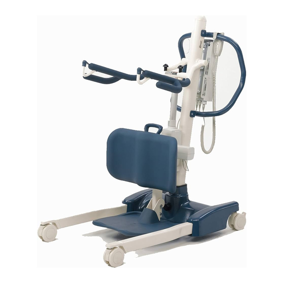
Invacare® Roze™ 3 Components ITEM Description Front Caster 3.1 Main Parts of the Lift Rear Caster with Brake Base Mast Control Unit with Battery Steering Handle Lift Arm Hook for Sling Manual Emergency Lowering Handgrip Actuator Knee Pad Foot Plate... -
Page 15: Accessories
WARNING! Accessories designed by other manufacturers Risk of Injury or Death have NOT been tested by Invacare. Use of Improperly attached, improperly adjusted, or Non-Invacare accessories may result in injury or damaged slings can cause the patient to fall or damage. - Page 16 Invacare® Roze™ Available accessories WARNING! Stand Assist Sling – Before lifting the patient, make sure the bottom edge of the stand assist sling is positioned on the lower back of the patient and the patient’s arms are outside the stand assist sling. The...
-
Page 17: Setup
(service) parts, may cause injury or damage. – Assembly MUST be performed only by qualified personnel. – Use only Invacare parts in the assembly of this lift. The lift components are manufactured to specifications that assure correct alignment of all parts for safe functional operation. -
Page 18: Assembling The Mast To The Base
There are no tools required to assemble the stand assist lift. If there are any issues or questions during assembly, contact a local Invacare representative. Refer to the contact information in the back of this manual. 4.3 Assembling the Mast to the Base... - Page 19 Setup 5. Connect the mast assembly cable F to the base cable The mast assembly A may be removed from the base B for storage or transporting. The mast assembly MUST be properly secured to the base WARNING! assembly before use. Risk of injury –...
-
Page 20: Assembling The Knee Pad To The Mast Assembly
Invacare® Roze™ 4.4 Assembling the Knee Pad to the Mast 4.5 Assembling the Foot Plate to the Mast Assembly Assembly The knee pad may be removed from the stand assist lift for storage or transporting. The knee pad MUST 1. Rotate the foot plate A up and place the hooks be properly secured to the mast assembly before use. -
Page 21: Checking The Service Light
Contact approximate 3 mm (1/8-inch) gap between the screw Refer to your local head and the wall. Resetting Invacare 5. Install the battery charger with mounting bracket onto the Service dealer or the bottom mounting screw. Light in the representative 6. -
Page 22: Attaching The Battery Charger Mounting Bracket To The Mast Assembly
Invacare® Roze™ 7. Install the two remaining mounting screws D through A = Battery and battery charger shown in place on the mounting bracket and into the wall. Tighten mast assembly. securely. 8. Plug the battery charger into the wall electrical outlet. -
Page 23: Usage
Usage 5.3 Closing/Opening Legs of the Lift 5 Usage WARNING! 5.1 Introduction Risk of Death, Injury or Damage The lift could tip and endanger the patient and The operation of the stand assist lift is an easy and safe assistants. procedure. -
Page 24: Closing/Opening Legs Of The Electric Lift
Refer to the safety information in Closing/Opening assistants. Legs of the Lift before performing this procedure. – Invacare recommends that the rear casters be left unlocked during lifting procedures to 1. To close the legs of the allow the patient lift to stabilize itself when the... -
Page 25: Activating A Mechanical Emergency Release
Usage 5.5 Activating a Mechanical Emergency Release 5.5.2 Secondary Emergency Release There are two types of mechanical emergency release — primary and secondary. 5.5.1 Primary Emergency Release It is recommended that the primary emergency release be used. The secondary emergency release is only a back-up to the primary emergency release. -
Page 26: Performing An Emergency Stop
2. To reset, rotate the emergency button clockwise. 5.7 Charging the Battery Invacare recommends the battery be recharged daily to prolong battery life. There are two different methods to charge the battery. One method uses a power cord that attaches to the control box, and the other requires the battery to be mounted to the battery charger. - Page 27 Usage The LEDs indicate the battery state: Control Box Battery Indicator Battery State Hand Control Battery Description Indicator Full Charge The battery is OK — no need for charging (100–50%). The third LED is GREEN. Partial Charge The battery needs to be charged (50–25%). The second LED is YELLOW.
-
Page 28: Using A Power Cord To Charge The Battery
Invacare® Roze™ 5.7.2 Using a Power Cord to Charge the Battery WARNING! Risk of Death, Injury or Damage The battery is capable of being charged while attached to the lift. – DO NOT activate the emergency stop when attempting to charge the battery. The battery will not charge if the emergency stop is activated. -
Page 29: Using The Battery Charger To Charge The Battery
Usage 5.7.3 Using the Battery Charger to Charge the Battery CAUTION! Mounting the battery improperly may cause injury or damage. – Make sure there is an audible click when mounting battery on the battery charger to confirm proper mounting. 3. Place the battery on the battery charger D as shown. Make sure there is an audible click. -
Page 30: Lifting The Patient
– The Invacare patient lift is NOT a transport lift in front of the patient and lift the patient device. It is intended to transfer an individual off the surface of the bed. - Page 31 – ALWAYS be aware of the location of the hand times to push or pull the product. control cord in relation to the patient and – Avoid using the product on an incline. Invacare caregivers. recommends that the product only be used on –...
-
Page 32: Preparing To Lift
Invacare® Roze™ 6.2 Preparing to Lift WARNING! Risk of Injury or Damage WARNING! – Use the sling that is recommended by a Risk of Injury or Damage healthcare professional for the comfort and – Ensure equipment used with the lift is of safety of the individual that is being lifted. - Page 33 Lifting the Patient 3. Position the patient into the sling A. Refer to the sling 6. Use the steering handle B to push the patient lift into user manual. position. WARNING! – When using the lift in conjunction with beds or wheelchairs, be aware of the position of the lift in relationship to those other devices so that the lift does not become entangled.
-
Page 34: Attaching The Sling To The Lift
Improperly attached, improperly adjusted, or damaged slings can cause the patient to fall or cause injury to assistants. – Use an Invacare approved sling that is recommended by the individual’s doctor, nurse or medical assistant for the comfort and safety of the individual being lifted. - Page 35 Lifting the Patient WARNING! WARNING! Risk of Injury or Death Stand Assist Sling Improperly attached, improperly adjusted, or – DO NOT use the stand assist sling in damaged slings can cause the patient to fall or combination with the patient lift as a transport cause injury to assistants.
-
Page 36: Lifting The Patient
Patient section of the manual Raising/Lowering the Lift in the Usage section of the manual Invacare recommends at least two (2) individuals assist in transferring the patient using this product. 1. Move the lift to the patient area, open legs and prepare to lift. - Page 37 Lifting the Patient 3. Position the patient’s knees securely against the knee 6. Instruct the patient to lean back into the sling. pad A. Properly position their feet on top of the foot plate B. 7. Press the UP arrow button on the hand control to raise the patient above the stationary object.
-
Page 38: Transferring From The Lift To A Bed
Invacare® Roze™ 8. Using the steering handle, move the lift away from the 6.4.1 Transferring from the Lift to a Bed stationary object. 1. Perform the steps in the Lifting the Patient section of the manual before transferring to a bed. -
Page 39: Transferring From The Lift To A Commode
6. Unhook the sling from all attachment points on the stand assist lift. The Invacare stand assist lift is NOT intended as a transport device. If the bathroom facilities are NOT near the bed or if the lift cannot be easily... - Page 40 Invacare® Roze™ 3. Press the UP arrow button on the hand control to 5. Press the DOWN arrow button to lower the patient elevate the patient high enough to suspend above the onto the commode. commode. Refer to Raising/Lowering the Lift in the Usage section of the manual.
- Page 41 Lifting the Patient 8. If the sling has been unhooked from the lift, instruct 10. Unlock the rear casters and move the lift away from the patient to lift their feet off of the foot plate. Assist the commode. the patient if necessary. If the patient will be remaining in the sling while using the commode, disregard STEPS 12–14.
-
Page 42: Transferring From The Lift To A Wheelchair
Invacare® Roze™ 6.4.3 Transferring from the Lift to a Wheelchair 3. Position the patient over the wheelchair. There should be one assistant behind the wheelchair to ensure that WARNING! the patient is as far back as possible into the seat for Risk of Injury proper positioning. -
Page 43: Troubleshooting
The connecting terminals are damaged. Replace the battery pack. Refer to Charging the Battery. Electric actuator in need of service or Refer to Replacing the Electric Actuator load is too high. or Replacing the Leg Actuators. Contact your Dealer or Invacare representative. 1195052-B... - Page 44 Initial assembly — Reset the service manufactured or initially assembled. light. Refer to Resetting the Service Light. After initial assembly — Service the lift. Contact your local Invacare dealer. If problems are not remedied by the suggested means, please contact your dealer or Invacare. 1195052-B...
-
Page 45: Maintenance
– Regular maintenance of patient lifts and accessories is necessary to assure proper operation. – Use only Invacare parts in the assembly of this patient lift. The base, legs, mast, boom or lift arms, and pump or actuator assembly are manufactured to specifications that assure correct alignment of all parts for safe, functional operation. -
Page 46: Wear And Tear Items
Please refer to the HSE web site for guidance www.hse.gov.uk. Invacare reserves the right to ask for any item back that has an alleged defect in workmanship. See the Warranty that The person responsible for the equipment must ensure shipped with the product for specific warranty information. -
Page 47: General Maintenance
Follow the maintenance procedures described in this manual to keep your patient lift in continuous service. The Invacare lift is designed to provide safe, efficient and satisfactory service with minimum care and maintenance. It is important to inspect all stressed parts, such as slings, lift arms and any pivot points for signs of wear, cracking, fraying, deformation or deterioration. -
Page 48: Daily Inspection
Invacare representative immediately. Visually inspect the patient lift. Check all parts for external damage or wear. If damage is found, do not use. Contact your Dealer or Invacare representative immediately. Check the emergency lowering function (both electrical and/or mechanical). Check all parts for external damage or wear. -
Page 49: Safety Inspection Checklist
Maintenance 8.1.7 Safety Inspection Checklist THE LIFT ARMS AND LINKAGE Periodic inspections should be performed by a qualified Check all hardware and attachment points. technician. Inspect for bends or deflections. Inspect bolted joints of the lift arms for wear. Date of Inspection: Inspect to ensure that the lift arms are centered between the base legs. -
Page 50: Lubricating The Lift
4. Casters lubrication. The casters MUST swivel and roll smoothly. Apply The Invacare lift is designed for minimum maintenance. lubricant to the ball bearing swivel of the casters However, a yearly check and lubrication should ensure once a year. Apply more frequently if the casters are continued safety and reliability. -
Page 51: Resetting The Service Light
Light section. If the service light is required to be set for a period shorter than 12 months, a special hand control and further instructions are required. Contact Invacare to order this hand control and instructions. 8.5 Replacing the Electric Actuator This procedure should only be performed by a qualified technician. - Page 52 Invacare® Roze™ 1. Unplug the electric actuator A from the control box on the mast assembly. Thread the actuator lead through the actuator lead routing hole B in the mast assembly. 2. Remove the hardware that secures the top of the electric actuator to the lift arm actuator mounting bracket C.
-
Page 53: Replacing The Leg Actuators
Maintenance 8.6 Replacing the Leg Actuators 1. Test the operation of the legs: • Press the close button on the hand control to close This procedure should only be performed by a the legs. qualified technician. • Press the open button on the hand control to open the legs. -
Page 54: Replacing Rear Casters
Invacare® Roze™ 9. To replace the actuator(s), reverse STEPS 5-7. 1. Place the lift on its side. 10. Reverse STEPS 3–4 to replace the small base covers and 2. Remove the bolt A and locknut B that secure the large base cover. -
Page 55: Adjusting The Knee Pad Height
Maintenance 1. Place the lift on its side. 2. Remove the bolt A, bearing C and locknut B that secure the existing front caster assembly D to the front caster bracket E. 3. Install the bolt through the front caster bracket and the new front caster assembly. -
Page 56: Technical Data
Invacare® Roze™ 9 Technical data 9.1 Patient Lift 1195052-B... - Page 57 Technical data Maximum height Reach from base 161 cm capacity (k) with legs spread to 22,2 cm Lowest position 70 cm (c) 94 cm (min. height) (l) Minimum Internal width at Clearance of Base 3,7 cm 86,5 cm maximum reach (q) from the Floor (s) Total width (closed) Maximum...
- Page 58 Charger Input 100-240V AC ~ 50/60 Hz Expected lifetime 8 years (voltage supply) Charger The Roze lift passes the “velocity of Output/Charging 29.5V DC 2.9 Ah Max 6 hours lifting and lowering” in the ENISO10535 Lifting Speed Time (<0.15 m/s under maximum load and Audio/Visual Low <0.25 m/s unloaded)
-
Page 59: Environmental Conditions
Storage temperature above 0°C 9.3.1 Electric Lifts Storage air humidity less than 60% Invacare® is continuously working towards ensuring that the Storage atmospheric 700 hPa to 1060 hPa company’s impact on the environment, locally and globally, pressure is reduced to a minimum. We comply with the current environmental legislation (e.g. -
Page 60: Electromagnetic Compatibility (Emc) Information
Invacare® Roze™ 9.4 Electromagnetic Compatibility (EMC) Information Medical Electrical Equipment needs to be installed and used according to the EMC information in this manual. This equipment has been tested and found to comply with EMC limits specified by IEC/EN 60601-1-2 for Class B equipment. -
Page 61: Electromagnetic Compatibility (Emc)
Technical data 9.4.1 Electromagnetic Compatibility (EMC) Guidance and manufacturer´s declaration – electromagnetic emission The patient lift is intended for use in the electromagnetic environment specified below. The customer or the user of the patient lift should assure that it is used in such an environment. Emissions test Compliance Electromagnetic environment - guidance... - Page 62 Invacare® Roze™ ± 2 kV for power supply ± 2 kV for power supply Electrostatic lines lines Mains power quality should be that of a typical Transient / Burst commercial or hospital environment. ± 1 kV for input/output ± 1 kV for input/output...
- Page 63 Technical data Portable and mobile RF communications equipment should be used no closer to any part of the patient lift including cables, than the recommended separation distance calculated from the equation applicable to the frequency of the transmitter. Recommended separation distance: Conducted RF IEC 61000-4-6 Radiated RF...
- Page 64 Invacare® Roze™ Field strengths from fixed transmitters, such as base stations for radio (cellular/cordless) telephones and land mobile radios, amateur radio, AM and FM radio broadcast and TV broadcast cannot be predicted theoretically with accuracy. To assess the electromagnetic environment due to fixed RF transmitters, an electromagnetic site survey should be considered. If the measured field strength in the location in which the patient lift is used exceeds the applicable RF compliance level above, the patient lift should be observed to verify normal operation.
- Page 65 Technical data For transmitters rated at a maximum output power not listed above the recommended separation, distance d in metres (m) can be estimated using the equation applicable to the frequency of the transmitter, where P is the maximum output power rating of the transmitter in watts (W) according to the transmitter manufacturer.
-
Page 66: After Use
Maintenance section of the manual. Always provide the user manual with the reused or refurbished lift. Contact information for your local Invacare office is located inside the back cover of this manual. 1195052-B... - Page 67 Notes...
- Page 68 Notes...
- Page 69 Invacare nv • Autobaan 22 • B-8210 Loppem • Tel: (32) (0)50 83 10 10 • Fax: (32) (0)50 83 10 11 • belgium@invacare.com • www.invacare.be Danmark Invacare A/S • Sdr. Ringvej 37 • DK-2605 Brøndby • Tel: (45) (0)36 90 00 00 • Fax: (45) (0)36 90 00 01 • denmark@invacare.com • www.invacare.dk Deutschland Invacare GmbH •...
- Page 70 Sverige Invacare AB • Fagerstagatan 9 • S-163 53 Spånga • Tel: (46) (0)8 761 70 90 • Fax: (46) (0)8 761 81 08 • sweden@invacare.com • www.invacare.se United Kingdom Invacare Limited • Pencoed Technology Park, Pencoed, Bridgend CF35 5AQ • Tel: (44) (0)
- Page 72 Invacare Corporation EU Representative Manufacturer Invacare Portugal, Lda One Invacare Way Invacare Portugal, Lda Rua Estrada Velha n° 949 Elyria, Ohio USA Rua Estrada Velha n° 949 4465–784 Leça do Balio 44035 4465–784 Leça do Balio Portugal 800–333–6900 Portugal Tel: (351) (0)225 1059 46/47...
Need help?
Do you have a question about the Roze and is the answer not in the manual?
Questions and answers