
Related Manuals for Invacare Robin EVO


Summary of Contents for Invacare Robin EVO
- Page 1 Invacare® Robin® EVO en Ceiling Hoist Service Manual PROVIDER: Keep this manual. The procedures in this manual MUST be performed by a...
-
Page 2: Table Of Contents
All rights reserved. Republication, duplication or modification in whole or in part is prohibited without prior written permission from Invacare. Trademarks are identified by ™ and ®. All trademarks are owned by or licensed to Invacare Corporation or its subsidiaries unless otherwise noted. -
Page 3: General
1 General 1 General 1.2 Symbols in this Manual 1.1 Introduction Symbols and signal words are used in this document and apply to hazards or unsafe practices which could result in personal This document contains important information about assembly, injury or property damage. See the information below for adjustment and advanced maintenance of the product. To definitions of the signal words. ensure safety when handling the product, read this document and the user manual carefully and follow the safety DANGER! instructions. Indicates a hazardous situation that will result in serious injury or death if it is not avoided. Find the user manual on Invacare’s website or contact your Invacare representative. See addresses at the end of this WARNING! document. Indicates a hazardous situation that could result in Invacare reserves the right to alter product specifications serious injury or death if it is not avoided. without further notice. Before reading this document, make sure you have the latest CAUTION! version. You find the latest version as a PDF on the Invacare Indicates a hazardous situation that could result in website. minor or slight injury if it is not avoided. Previous product versions may not be described in this manual´s current revision. If you require assistance, please NOTICE! contact Invacare. -
Page 4: Safety
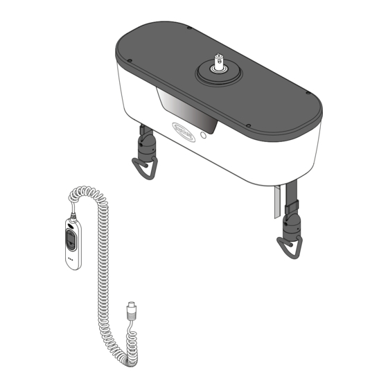
Invacare® Robin® EVO 2 Safety 2.2 Main parts of the ceiling hoist 2.1 General Safety Information WARNING! Risk of injury or damage to property — The procedures in this manual must only be performed by a qualified technician. — Use only original accessories and spare parts. — Do not handle this product or any available optional equipment without first completely reading and understanding these instructions and any additional instructional material such as user manuals, installation manuals or instruction sheets supplied with this product or optional equipment. ... -
Page 5: Setup
3 Setup 3.1 Installing the ceiling hoist The ceiling hoist must be mounted to a rail system to perform its intended use. The rail system must be installed and approved according to ISO 10535 by a qualified technician. This ceiling hoist requires a trolley, holding it inside the rail system. The trolley must be pre-installed by a qualified technician. Refer to EC-Track installation manual. WARNING! Risk of injury or damage Non-original or incorrect rail system may affect the function and safety of this product. — If a rail system from another manufacturer is intended to be used with the Invacare ceiling hoist, a risk assessment for the combination/compatibility of both products shall be performed by the responsible person/organization for the combination. To mount the ceiling hoist to the trolley, do the following: 1. Locate the hoist trolley B at the Ø 32 mm round recess in the rail A. 2. Lift the hoist and push the suspension pin through the trolley opening. 3. Turn the hoist by 90 degrees to fix it in the trolley. Keep pushing the device to avoid the free rotation of the pin when fixing in the trolley. ... -
Page 6: Maintenance
Invacare® Robin® EVO 4 Maintenance 4.2.3 Cleaning instructions 4.1 General maintenance information NOTICE! — The product does not tolerate cleaning in automatic washing systems, with high-pressure CAUTION! cleaning equipment or steam. Risk of injury or damage — Do not perform any maintenance or service Cleaning the lift procedures while the product is in use. Method: Wipe off with a damp cloth or soft brush. Follow the maintenance procedures described in this manual to Solvent/chemicals: Ordinary household cleaning agent and keep your product in continuous service. water. 4.2 Cleaning and Disinfection Drying: Wipe dry with a soft cloth. Cleaning the sling 4.2.1 General Safety Information... -
Page 7: Charging The Battery
It is not possible to use the hoist while the battery is charging. 1. Finish the current lift in progress. 2. Move the ceiling hoist to the charging station. 3. Assure that the hand control and charging station are clean and dry before charging starts. 4. Place the hand control into the charging station and make sure that the power supply adapter is plugged in. A blinking orange led on the hand control indicates it is charging. During the charging process, the LEDs of the hand control are permanently on and blinking. 5. When fully charged, the indicator lights on the hand control turn green (static light). As long as the ceiling hoist is not in use, leave the hand control in the charging station. The charging LEDs do not go into sleep mode until the charge has reached full. 6. To use the ceiling hoist, remove the hand control from the charger. Keeping the batteries charged guarantees hoist functionality and maintains the battery to ensure a long lifetime. If the ceiling hoist will not be used for more than 1 week, Invacare recommends disconnecting the charger and pulling the emergency stop. The charger is connected to a power supply adapter which, in turn, connects to the mains with a mains plug. Make sure that the mains plug is accessible and can be unplugged if required. 60133893-A... -
Page 8: Servicing
Invacare® Robin® EVO Disassemble the product and its components, so the different 5 Servicing materials can be separated and recycled individually. The disposal and recycling of used products and packaging must 5.1 Service interval comply with the laws and regulations for waste handling in each country. Contact your local waste management company WARNING! for information. Risk of injury or damage Service must be performed only by a qualified 5.4 Tightening torques technician. — Contact your Invacare provider for service. NOTICE! Do not overtighten the mounting hardware as this Service must be performed at least every 12 months unless might cause damage to the product. otherwise stated in local requirements. The frequency of inspection must be increased, if the product is If not otherwise stated in the specific instructions the following continuously exposed to high humidity, high condensation and guidelines apply: corrosives (e.g. chlorine or ammonia gases), to prevent product impairment. Thread Setting torque 1.9 ± 0.5 Nm... -
Page 9: Periodic Inspection Checklist | Ec-Track System, Gantry And Robin Evo
5 Servicing 5.5 Periodic Inspection Checklist | EC-Track System, Gantry and Robin EVO In accordance with ISO 10535. CAUTION! Risk of injury and damage to property Failure to ensure an adequate Periodic Inspection of the product can compromise the safety of people and property. — A periodic inspection of the product must be performed at least every 12 months unless otherwise stated in local requirements. — The frequency of inspection must be increased if the product is continuously exposed to high humidity, high condensation and corrosives (e.g., chlorine or ammonia gases), to prevent product impairment. — Inspections MUST be performed by a qualified person who is acquainted with the design, use and care of the product. — The inspection record MUST be recorded in the logbook and reported to the owner. - Page 10 1.24 Place a label with the date for next inspection (MM-YYYY) on the Tracks. Label Example: Date for Next Inspection Does this inspection include the Robin Evo? □ Yes (Complete the following section). □ No (Skip to the 3. Final Steps and make sure to check the hoist’s manufacturer Instructions / Installation Manual). 2. Checkpoints | Robin EVO Comments 2.1 Check for broken, missing or misaligned parts. 2.2 Product Label is present and legible (write SN on the comments section). 2.3 The hoist is marked with the maximum SWL. ...
- Page 11 5 Servicing 2. Checkpoints | Robin EVO Comments 2.13 Check tape guide cylinders. 2.14 The hand control is connected correctly. 2.15 The hand control is functional and in good conditions. Electrical Connections 2.16 All cables are intact. 2.17 No signs of rupture on cables and on isolation. 2.18 Clamping and mechanical function of micro switches work correctly. 2.19 The charger does not have signs of damage and is functional. 2.20 Check that battery is charged when connecting the hand control ...
-
Page 12: Instructions
8). WARNING! Risk of injury or damage to property — Always perform and fill out the Periodic Inspection Checklist (Refer to 5.5 Periodic Inspection Checklist | EC-Track System, Gantry and Robin EVO, page 9). Check after installation: □ Check if the hand control is locked (does not fall). 6.1 Dismounting the ceiling hoist □ Make sure the hand control is working. 1. Lift the hoist slightly and push the suspension pin out of its ... -
Page 13: Advanced Th12 Tool Hand Control
6 Instructions 6.3 Advanced TH12 Tool Hand Control The advanced TH12 hand control has twelve buttons, the combinations shown below allow to perform the described actions. Layout Buttons Action Move up both straps (M1 & M2) Move down both straps (M1 & M2) Absolute weight calibration: 0 kg Absolute weight calibration: 200 kg Setting of M1 photo sensor value Setting of M2 photo sensor value Relative calibration: 0 kg Setting of automatic test mode: set the pause time when at upper limit (1~250 seconds) Setting of automatic test mode: to set as upper limit SW10 Setting of automatic test mode: to set as lower limit SW11 Start the automatic test Setting of automatic running test mode: the pause time at SW12 lower limit (1~250 seconds) SW1+SW2 Reset (Press for 3 seconds) SW1+SW3 Move up M1 strap (Press for 3 seconds) SW2+SW4 Move up strap of M2 (Press for 3 seconds) SW3+SW4 Enter ‘Engineering mode’ (Press for 3 seconds) SW5+SW6 Enter/Save&Exit ‘Photo sensor setting mode’... -
Page 14: Removing And Assembling The Top Cover
Invacare® Robin® EVO Removing and assembling the Top 6.5 Replacing the Top Cover Kit and the Cover Rubber Gasket Items Quantity Tools: Slotted screwdriver; TORX T20 screwdriver Top Cover 1. Identify the four plugs on the top cover. Top Cover Screws Top Cover Plugs Rubber Gasket 2. Using a thin slotted screwdriver remove all four plugs (take care to avoid any damage to the cover). Tools: Slotted screwdriver; TORX T20 screwdriver 1. Remove the old top cover. Refer to 6.4 Removing and assembling the Top Cover, page 14. -
Page 15: Replacing The Oled Display Kit
6 Instructions 4. Tighten all four screws on the top cover. 3. Remove the cable plug. 5. End the procedure by manually applying the new plugs. Check after installation: 4. Replace the display module. □ Make sure the cover is attached properly with all 4 screws 5. Reattach the cable plug. and there are no loose parts. There shall be no gap between cover, main body and the oled display of the ceiling hoist. Check after installation: □ Make sure that all the plugs covering the screws are fitted. □ Press a hand control button to activate and validate if the □ Do a full lifting cycle to check if the device operates properly. display is working. 6.6 Replacing the OLED Display Kit 6.7 Replacing the Photo Sensor Kit Items Quantity Items... -
Page 16: Replacing The Mechanical Emergency Plugs
Invacare® Robin® EVO 2. Unplug the cable from the photo sensor. Check after installation: □ Perform a full strap cycle and check that there are no errors. The strap outlet must stop automatically when the strap is completely out. □ With the straps completely rolled in, block the outlet of one strap and press the down button. The device must stop showing ‘strap jam’ error. Check the height difference relatively to the free strap. If longer than 500 mm, the sensor sensitivity parameter must be adjusted. Replacing the Mechanical Emergency Plugs Items Quantity Mechanical Emergency Plugs 3. Remove the four side screws. Tools: Slotted screwdriver 1. Identify the plugs on the front and back of the device. 4. Install new parts in the reverse order. The Photo sensor’s function is not limited to detecting the white square. It also detects when the strap starts to loosen inside the device (as it gets close to the sensor). It might be required to re-program the new sensitivity parameters of the photo sensor. -
Page 17: Replacing The Red Emergency Strap
6 Instructions 4. End the procedure by fitting the plugs in tightly with your 3. Locate the power plug and disconnect it, to avoid fingers. undesirable gear movements. Check after installation: □ Make sure that all the plugs are fitted. 6.9 Replacing the Red Emergency Strap Items Quantity Red Emergency strap 4. Locate the four screws securing the chassis of the device to its plastic casing. 1. Remove the red emergency strap (including its metal ring). 2. Install new parts in the reverse order. Notes on the TORX T25 screwdriver: — To reach the screws - on the bottom of the Check after installation: casing - a screwdriver with a minimum reach ... -
Page 18: Replacing The Battery Module Kit
Invacare® Robin® EVO 6. Locate the cable plug from the LED PCB connecting to the main board and unplug it. Tools: PH1 screwdriver CAUTION! Risk of damage to the property Incorrect installation of the cables may cause malfunction of the product. — Please DO NOT change the order of the cables. — Pay attention to the highlighted Photo Sensor plugs before removing the cables. 1. Remove all plugs that remain connected to the battery module. 7. Pull up the chassis out of the plastic shell. 2. Remove both screws and washers that secure the battery module. 6.11 Replacing the Battery Module Kit 3. Apply the new battery module. 4. Repeat the process in the reverse order. -
Page 19: Replacing The Gear Motor
6 Instructions Tools: PH1 screwdriver 1. Locate the main PCB module. Tools: HEX key 3 mm 1. Locate gear motor TGM7. 2. Remove all plugs. 3. Remove the three screws and washers securing the PCB There are two gear motors on the device. module to the chassis. Each one of them is located on opposite sides of the chassis. 2. Locate and disconnect all plugs. 3. Locate and remove both HEX 3 mm screws securing the gear motor to the chassis. 4. Apply the new PCB module. 5. Repeat the process in the reverse order. 4. Apply the new gear motor. Check after installation: □ All buttons and functions are working. Apply grease if necessary. Recommended high load-bearing and extreme ... -
Page 20: Replacing The Hand Control Plug Or Led Light Pcb
Invacare® Robin® EVO 5. Remove the hand control plug (secured by a 17 mm nut). 6.14 Replacing the Hand Control Plug or Led Light PCB Items Quantity Led Light Shield Led Light Diffuser 6. Locate and remove the two torx T10 screws. Led PCB Hand Control Plug 7. Remove the LED PCB and revert the assembly process. Check after installation: □ Press down or up button and check for blinking blue light. □ Remove the hand control and check for red blinking light. □ Insert the hand control and check for a single blink green Tools: T10 Torx Screwdriver; HEX key 17 mm light. 1. Starting off the empty lower part of the casing, locate its 6.15 Replacing the End Switch Kit six TORX T10 screws. -
Page 21: Replacing The Bottom Cover Kit
6 Instructions 2. Identify all four end switches (there are two on each side If any securing cable ties were cut off at the earlier of the module). stages of this process, make sure to re-apply new ones. Loose cables may prevent the correct installation of the battery module. Check after installation: □ Make sure that the End Switch is installed respecting the same orientation. □ Manually check that end switches can be activated pressing the swiveling inlet plastic parts. Listen carefully for the end switch clicking sound. □ Do not forget to re-apply the cable ties, if they were cut off in the earlier stages of this process. □ Perform a full lifting cycle and check that up movement stops when the hooks press on the swiveling inlet plastic part. 3. Remove the plugs connecting the End Switch to the main 6.16 Replacing the Bottom Cover Kit PCB (only of the End Switch you need to replace). Itens Quantity Bottom Cover Tools: T20 Torx Screwdriver; If necessary, cut off the securing cable ties until the cable is completely loose. In these cases, the To remove the bottom casing cover, it is mandatory to ... -
Page 22: Replacing The Strap With Hook Kit
Invacare® Robin® EVO 4. Remove the central axis. Tools: HEX key 3 mm; HEX key 6 mm; HEX key 5 mm; 10 mm socket wrench Make sure the strap is fully unrolled. If the strap is not fully extended outside the module, provide power supply to the PCB, and unroll the strap completely. 1. Manually, using the mechanical emergency, turn the gear 5. Remove the strap from inside the hook. clockwise until the screw securing the strap is aligned with the slit on the chassis, and there is no strap rolled around the gear cube. 6. Substitute the bottom cover. 2. Remove the 5 mm hex screw holding the nut on the 7. Repeat the process in the reverse order. opposite side of the gear. To be careful with the spacers to avoid letting Flatten the end of the strap before inserting it back them fall. into the hook, to facilitate this process. - Page 23 6 Instructions 4. To insert the new strap, it is necessary to relieve pressure 8. In the first phase, make the strap come out right after the on the one-way bearing. swivel inlet. 5. Locate and remove both HEX 3 mm shoulder screws securing the clamping springs (one at each end of one-way bearing). 6. Move the rollers away. 9. Reinsert the free end into the strap guide. 7. Insert the free end of the new strap from the swivel inlet. Flattening the end makes it easier to insert. 10. Push until the free end appears between the rod and the idler. 60133893-A...
- Page 24 Invacare® Robin® EVO 11. Align the strap loop until it is concentric with the fixing 14. Retighten the shoulder screws holding the springs. screw hole. 15. Check that they are properly tightened.. 12. Tighten the screw and nut. Attention to the spacer Check after installation: orientation. □ Test the ceiling hoist with one lifting cycle with no load. Perform the strap reset procedure. □ Test the ceiling hoist with one lifting cycle with SWL. 13. Manually, turn the gear counterclockwise using the Emergency Mechanical System until the white marker has completely passed the photosensor. 60133893-A...
-
Page 25: Troubleshooting
Reduce the load and try again. Symbol on display and indicator light flashing red. Strap is loose or jammed inside the lifting Pull the lifting straps down to stretch them module. and try again. Symbol on display and indicator light flashing red. Strap length reference lost (after using the Perform a system reset. Refer to the user emergency lowering function). manual. Symbol on display and indicator Check the connection of the hand control. light flashing red. Hand control is not properly connected or If a proper connection of the hand control is defective. does not solve the problem, contact your Invacare provider for service. Symbol on display and indicator light flashing red. Do not use the ceiling hoist and contact Failure of the internal weight sensor. your Invacare provider for service. Remove any possible blockage at the strap Symbol on display and indicator inlet (e.g. twisted straps or other objects light flashing red. Strap blockage detected or failure of the touching) and perform a system reset. internal motor sensor. Refer to the user manual. If the error persists, do not use the ceiling hoist and contact your Invacare provider for service. Symbol on display and indicator light flashing red. Do not use the ceiling hoist and contact Failure of the internal strap length sensor. - Page 26 Invacare® Robin® EVO Malfunction Possible Cause Solution Do not use the ceiling hoist and contact Hand control defective. your Invacare provider for service. Lifting straps will only move down and not up. Perform a system reset. Refer to the user Strap length reference was lost. manual. Do not use the ceiling hoist and contact Hand control defective. your Invacare provider for service. Lifting straps will only move up and not down. Perform a system reset. Refer to the user Strap length reference was lost. manual. Check that the hook rotate freely and Lifting hooks do not turn freely enough. clean if necessary. Lifting straps are twisted and do not straighten out. Do not use the ceiling hoist and contact Straps are frayed. your Invacare provider for service. Lifting module emits excessive Do not use the ceiling hoist and contact Bearings, gearwheels or motor defective. noise when activated. your Invacare provider for service. System does not have power or battery is Charge the battery. Refer to 4.4 Charging No indicator light on lifting module.
-
Page 27: Technical Data
8 Technical Data 8 Technical Data Robin® EVO Lifting speed — 8.1 Dimensions and weight with a 200 kg 3.7 cm/s load Power Supply 36 V DC Voltage output 100 – 240 V AC, 50 / 60 Hz, 1A Voltage supply Protection class IP00 See product label and label on each electric device for correct protection class. The lowest IP classification decides the overall classification of the device. IPx4: Protected against water splashed from any direction. Dimensions IP24: Protected against objects larger than 12.5 mm and Robin® EVO protected against water splashed from any direction. IP44: Protected against objects larger than 1 mm and Hoist length (A) 505 mm protected against water splashed from any direction. - Page 28 Invacare UK Operations Limited Invacare Portugal, Lda Unit 4, Pencoed Technology Park, Rua Estrada Velha 949 Pencoed 4465-784 Leça do Balio Bridgend CF35 5AQ ...
Need help?
Do you have a question about the Robin EVO and is the answer not in the manual?
Questions and answers