
Related Manuals for Advantech MIC-3392


Summary of Contents for Advantech MIC-3392
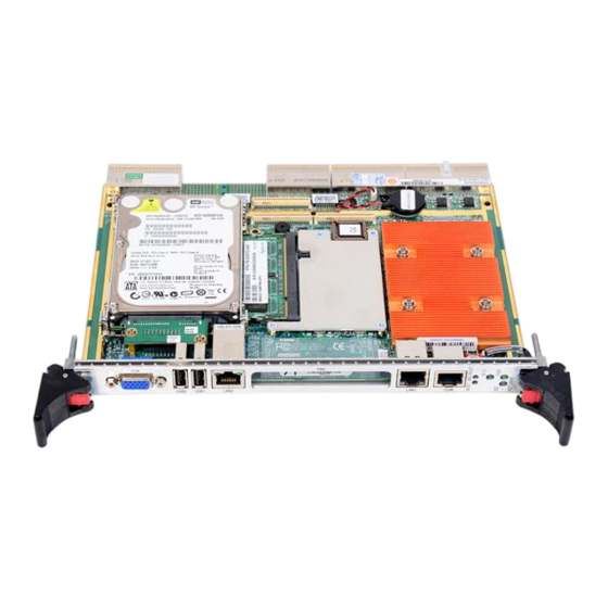
- Page 1 User Manual MIC-3392 6U CompactPCI Intel Core 2 Duo Processor Based Board with Dual PCIe GbE/DDR2/SATA/PMC...
- Page 2 No part of this manual may be reproduced, copied, translated or transmitted in any form or by any means without the prior written permission of Advantech Co., Ltd. Information provided in this manual is intended to be accurate and reliable. How- ever, Advantech Co., Ltd.
-
Page 3: Declaration Of Conformity
This product has passed the CE test for environmental specifications when shielded cables are used for external wiring. We recommend the use of shielded cables. This kind of cable is available from Advantech. Please contact your local supplier for ordering information. -
Page 4: Packing List
Please send all such - in writing to: support@advan- tech.com Packing List MIC-3392 all-in-one single board computer x1 Utility and user manual (PDF file) CD-ROM disc x1 CPU Heat sink (Assembled) x1 Thermal pad for CPU x1... -
Page 5: Safety Instructions
The sound pressure level at the operator's position according to IEC 704-1:1982 is no more than 70 dB (A). DISCLAIMER: This set of instructions is given according to IEC 704-1. Advantech disclaims all responsibility for the accuracy of any statements contained herein. - Page 6 Der arbeitsplatzbezogene Schalldruckpegel nach DIN 45 635 Teil 1000 beträgt 70dB(A) oder weiger. Haftungsausschluss: Die Bedienungsanleitungen wurden entsprechend der IEC- 704-1 erstellt. Advantech lehnt jegliche Verantwortung für die Richtigkeit der in die- sem Zusammenhang getätigten Aussagen ab. MIC-3392 User Manual...
- Page 7 Don't touch any components on the CPU card or other cards while the PC is on. Disconnect power before making any configuration changes. The sudden rush of power as you connect a jumper or install a card may damage sensitive elec- tronic components. MIC-3392 User Manual...
- Page 8 MIC-3392 User Manual viii...
-
Page 9: Table Of Contents
Table 1.14: SW6 IPMI programming setting........ 11 Table 1.15: SW7 - Master/Drone mode setting ......11 Table 1.16: SW1: BMC Reset Button & Platform Reset Button .. 11 Figure 1.2 MIC-3392 jumper, switch and connector locations... 12 Connector Definitions................12 Table 1.17: MIC-3392 connector descriptions......12 1.5.1... - Page 10 Figure 2.17Advanced Chipset Setting ........34 2.8.1 North Bridge Chipset Configuration ..........34 Figure 2.18North Bridge Configuration........34 2.8.2 South Bridge Configuration............35 Figure 2.19South Bridge Configuration ........35 Exit Option ....................36 Figure 2.20Exit Option..............36 MIC-3392 User Manual...
- Page 11 Table A.8: BT1 CMOS battery ........... 52 Table A.9: CN10 CF socket ............52 Table A.10:CN4 SATA daughter board connector...... 53 Table A.11:RJ1 LAN1 Connector..........53 Table A.12:RJ1 LAN1 Indicator ..........53 A.5.1 M/D, PWR & IDE/Hot-swap LEDs..........54 MIC-3392 User Manual...
- Page 12 C.2.3 Watchdog Disable Register ............59 Table C.4: Watchdog [7:0] (LPC I/O address: 444H)....59 Table C.5: Version [7:0] (LPC I/O address: 445H)..... 59 C.2.4 Geography Address (GA) ............59 Table C.6: GA [7:0] (LPC I/O address: 447H)......59 MIC-3392 User Manual...
-
Page 13: Chapter 1 Hardware Configuration
Chapter Hardware Configuration This chapter describes how to configure MIC-3392 hardware. -
Page 14: Introduction
The MIC-3392 is compliant with PICMG 2.0 Rev. 3.0. It supports a 64-bit / 66 MHz or 33 MHz PCI bus for up to 8 compactPCI slots at 3.3 V or 5 V VIO. The MIC-3392 is hot-swap compliant (PICMG 2.1) and conforms to the CompactPCI Packet Switching Backplane specification (PICMG 2.16) as well as the CompactPCI System Manage-... -
Page 15: Cpu
1.2.2 The MIC-3392 supports the latest Intel Core Duo/Solo and Intel Core 2 Duo proces- sor family with clock frequencies up to 2.16 GHz and a Front-Side Bus (FSB) up to 667 MHz. Intel Core Duo processors are validated with the Mobile Intel 945GM/945GME Express chipset. -
Page 16: Memory
1.2.6 Memory The MIC-3392 has up to 2 GB of onboard non-ECC DDR2 memory. In addition, an SODIMM socket supports up to 2 GB of the following types of memory. Table 1.3: SODIMM Types (Non-ECC) Brand Size Speed Vendor PN... -
Page 17: Ethernet
J3 connector. The onboard SATA port is only available on the single PMC ver- sion of the MIC-3392. The SATA2 interface is connected to the rear I/O module via the J5 connector and is reserved for user customized designs. Currently, Advan- tech's compatible RIO modules provide the SATA1 interface. -
Page 18: Mechanical And Environmental Specifications
1.2.16 CompactPCI Bridge The MIC-3392 uses a PLX PCI-6254 (Hint HB6) universal bridge as a gateway to an intelligent subsystem. When configured as a system controller, the bridge acts as a standard transparent PCI-to-PCI bridge. As a peripheral controller it allows the local MIC-3392 processor to configure and control the onboard local subsystem indepen- dently from the CompactPCI bus host processor. -
Page 19: I/O Connectivity
The keyboard and mouse is routed to the rear I/O module 1.2.21 RTC and Battery The RTC module keeps the date and time. On the MIC-3392 the RTC circuitry is con- nected to a battery source (CR2032M1S8-LF, 3 V, 210 mAH). 1.2.22... -
Page 20: Hpet And Io/Apic
1.2.23 HPET and IO/APIC The MIC-3392's built-in south bridge, the ICH7, provides features to support High Precision Event Timer (HPET) registers and I/O Advanced Programmable Interrupt Controller (APIC). The ICH7 timer registers are memory-mapped in a non-indexed scheme. The choice of address range will be selected by configuration bits in the HPET. -
Page 21: Jumpers And Switches
Table 1.4 and table 1.5 list the jumper and switch functions. Figure 1.2 illustrates the jumper and switch locations. Read this section carefully before changing the jumper and switch settings on your MIC-3392 board. Table 1.4: MIC-3392 jumper descriptions Number... -
Page 22: Clear Cmos (Jp1)
SW5-1 selects the LAN port that is used for Serial Over LAN (SoL) functionality. The 10/100 LAN3 port is routed to the rear I/O but is not currently implemented on stan- dard Advantech Rear I/O modules. Table 1.11: SW5-2 SATA HDD channel setting (single PMC) -
Page 23: Table 1.13: Sw5-3 & Sw5-4: Com2 To Console Or Bmc
Table 1.15: SW7 - Master/Drone mode setting Default Master ON ON Drone OFF OFF The MIC-3392 default setting is Master. Table 1.16: SW1: BMC Reset Button & Platform Reset Button SW1-1 BMC Reset SW1-2 Reset (Platform Reset) MIC-3392 User Manual... -
Page 24: Figure 1.2 Mic-3392 Jumper, Switch And Connector Locations
Figure 1.2 MIC-3392 jumper, switch and connector locations Connector Definitions Onboard connectors link to external devices such as hard disk drives, keyboards or floppy drives. Table 1.11 lists the function of each connector and Figure 1.2 illustrates each connector location. -
Page 25: Vga Display Connector (Vcn1 Or Rear I/O)
“rotating media” IDE hard drive. The MIC-3392 BIOS includes an option to allow the board to boot from the flash disk. The CompactFlash socket is connected to the IDE interface and 5 V power. -
Page 26: Ethernet Configuration (Rj1/Rj2 Or Rear I/O Rj1)
PMCs or PMC modules). PMC1 connects to a 64-bit / 66 MHz, 3.3 V PCI bus. PMC2 connects to a 32-bit / 33 MHz PCI bus and is only available on the dual PMC version of the MIC-3392. Front panel access is provided for the PMCs that require I/O con- nectivity. -
Page 27: Installing The Cpu And Heatsink
MIC3392. Con- tact an Advantech local sales office or distributor for more information. The MIC-3392 should be fastened to a heat sink supporting the Intel Core 2 Duo. When the user installs the CPU, the following steps should be followed: Remove the screws from the solder side cover. -
Page 28: Cpu & Heatsink Installation Steps
1.7.1 CPU & Heatsink Installation Steps The MIC-3392 contains electrostatically sensitive devices. Please discharge your clothing before touching the assembly. Do not touch components or connector pins. We recommend that you perform assembly at an anti-static workbench. Check that the following components are close at hand: –... -
Page 29: Battery Replacement
Apply adhesive to the replaced battery cover and re-glue it to the board. Finally, replace the connector Software Support Windows XP, Windows 2003, Windows Vista and Fedora Linux 6 have been fully tested on the MIC-3392. Please contact your local sales representative for details on support for other operating systems. MIC-3392 User Manual... - Page 30 MIC-3392 User Manual...
-
Page 31: Chapter 2 Ami Bios Setup
Chapter AMI BIOS Setup This chapter describes how to configure the AMI BIOS. -
Page 32: Figure 2.1 Setup Program Initial Screen
BIOS settings and control the special features of the MIC-3392. The Setup program uses a number of menus for making changes and turning the special features on or off. This chapter describes the basic navigation of the MIC-3392 setup screens. -
Page 33: Entering Setup
BIOS supports your CPU. If there is no number assigned to the patch code, please contact an Advantech application engineer to obtain an up-to-date patch code file. This will ensure that your CPU's system status is valid. -
Page 34: Main Setup
Date using the <Arrow> keys. Enter new values through the keyboard. Press the <Tab> key or the <Arrow> keys to move between fields. The date must be entered in MM/DD/YY format. The time is entered in HH:MM:SS format. MIC-3392 User Manual... -
Page 35: Advanced Bios Features Setup
Advanced BIOS Features Setup Select the Advanced tab from the MIC-3392 setup screen to enter the Advanced BIOS Setup screen. You can select any of the items in the left frame of the screen, such as CPU Configuration, to go to the sub menu for that item. You can display an Advanced BIOS Setup option by highlighting it using the <Arrow>... -
Page 36: Cpu Configuration
CPU's built in automatic thermal throttling when the die temperature is very near to the temperature limits of the processor. If set to “Disabled” the BIOS disables this feature and the MIC-3392 will shut off automatically if the CPU overheats. The default setting is “Enabled”. -
Page 37: Lan & Smbus Configuration
This setting indicates whether remote management is performed by Advantech's MIC-3924A Chassis Management Module (CMM) or by an IPMI-enabled CMM such as the Advantech MIC-3927. The default setting is “BMC” which corresponds to IPMI- enabled CMM. Table 2.1: Select SMBus mode... -
Page 38: Ide Configuration
Four options are available: SATA Only, Reserved, “SATA Pri, PATA Sec” or PATA Only. 2.4.3.3 Primary and Secondary IDE Master and Slave While entering setup, BIOS auto detects the presence of IDE devices. This displays the status of auto detection of the four possible IDE devices. MIC-3392 User Manual... -
Page 39: Floppy Configuration
2.4.4 Floppy Configuration Figure 2.8 Floppy Configuration Floppy A: Select the type of floppy drive connected to the system. Floppy B: Select the type of floppy drive connected to the system. MIC-3392 User Manual... -
Page 40: Super I/O Configuration
Serial Port2 Address: Used to select Serial Port2 base addresses Parallel Port Address: Used to select Parallel Port base addresses – Parallel Port Mode: Used to select Parallel Port mode – Parallel Port IRQ: Used to select Parallel Port IRQ MIC-3392 User Manual... -
Page 41: Acpi Setting
Figure 2.10 ACPI Setting The options for “ACPI Aware O/S” are “Yes” or “No” in order to enable or disable ACPI support for the operating system. The default is “Yes”. 2.4.7 Hardware Health Configuration Figure 2.11 Hardware Health Configuration MIC-3392 User Manual... -
Page 42: Console Redirection Configuration
ICH COM1 or ICH COM2. The Optimal and Fail-Safe default setting is ICH COM1. 2.4.8.3 Serial Port Mode Select the baud rate you want the serial port to use for console redirection. The Opti- mal and Fail-Safe default setting is 115200 8, n, 1. MIC-3392 User Manual... -
Page 43: Pci/Pnp Setup
PCI/PNP Setup Select the PCI/PnP tab from the MIC-3392 setup screen to enter the Plug and Play BIOS Setup screen. You can display a Plug and Play BIOS Setup option by highlight- ing it using the <Arrow> keys. All Plug and Play BIOS Setup options are described in this section. -
Page 44: Boot Setup
Boot Setup Figure 2.14 Boot Setup 2.6.1 Boot Settings Configuration Figure 2.15 Boot Settings Configuration MIC-3392 User Manual... -
Page 45: Security Setup
Security Setup Figure 2.16 Password Configuration Select Security Setup from the MIC-3392 Setup main BIOS setup menu. All Security Setup options, such as password protection and virus protection, are described in this section. To access the sub menu for the following items, select the item and press <Enter>:... -
Page 46: Advanced Chipset Settings
Advanced Chipset Settings Figure 2.17 Advanced Chipset Setting 2.8.1 North Bridge Chipset Configuration Figure 2.18 North Bridge Configuration MIC-3392 User Manual... -
Page 47: South Bridge Configuration
Boots Graphic Adapter Priority: Select which graphics controller to use as the primary boot device. 2.8.2 South Bridge Configuration Figure 2.19 South Bridge Configuration USB 2.0 Controller: Enabled, Disabled Audio Controller: Auto, Azalia, AC'97 Audio and Modem, All Disabled MIC-3392 User Manual... -
Page 48: Exit Option
Select Discard Changes from the Exit menu and press <Enter>. 2.9.3 Load Defaults This loads the safe defaults values for the MIC-3392 which allows optimum function- ality and system performance, but may not work best for all computer applications. Select Load Defaults from the Exit menu and press <Enter>. -
Page 49: Chapter 3 Ipmi
Chapter IPMI This chapter describes IPMI con- figuration. -
Page 50: Introduction
Introduction The MIC-3392 fully supports the IPMI 2.0 interface and the PICMG 2.9 R1.0 specifi- cation. The Renesas H8S/2167 has been implemented as the IPMI controller / Base- board Management Controller (BMC) to run firmware and collect information. The MIC-3392 IPMI firmware is sourced from Avocent, a provider of proven and tested IPMI implementations in a wide range of mission-critical applications. -
Page 51: Ipmi Device Global Commands
3.3.2 BMC Device and Messaging Interfaces The BMC messaging interfaces comply with the Intelligent Platform Management Interface Specification, Version 2.0. The MIC-3392 provides 4 messaging interface channels. LPC/KCS channel: Connects the H8S/2167 to the system LPC bus. Firmware sets 1 host interface over LPC:KCS for SMS. -
Page 52: Table 3.4: Bmc Device And Messaging Commands
Set User Password 0x47 Master Write-Read 0x52 3.3.3 BMC Watchdog Timer Commands Table 3.5: BMC Watchdog Timer Commands BMC Watchdog Timer Commands NetFn Mandatory / Optional Reset Watchdog Timer 0x22 Set Watchdog Timer 0x24 Get Watchdog Timer 0x25 MIC-3392 User Manual... -
Page 53: Chassis Device Commands
Get PEF Capabilities 0x10 Arm PEF Postpone Timer 0x11 Set PEF Configuration Parameters 0x12 Get PEF Configuration Parameters 0x13 Set Last Processed Event ID 0x14 Get Last Processed Event ID 0x15 Alert Immediate 0x16 PET acknowledge 0x17 MIC-3392 User Manual... -
Page 54: Sel Device Commands
3.3.9 FRU data The MIC-3392 supports the IPMI FRU function to store accessible multiple sets of non-volatile Field Replaceable Unit (FRU) information in FRU EEPROM. The FRU data includes information such as serial number, part number, model and asset tag. -
Page 55: Sensors And Threshold Configuration
LNC,UC LNC,UC Note! A chassis intruder sensor is not used on the MIC-3392 platform. Power failure sensor type "C0h" indicates a power failure event. Apart from the following list of sensors, other sensors should be reinitial- ized when the system is powered on or reset. -
Page 56: Table 3.14: Sensor Device Commands
3.3.11 Serial over LAN The MIC-3392 supports Serial over LAN (SOL). This can be used for implementing a virtual remote serial terminal to enable user or remote software interaction with serial interfaces for operating system and management services. SOL is implemented as a payload type under the IPMI v2.0 “RMCP”+ protocol. -
Page 57: Bmc Reset
BMC Reset The BMC can initiate a graceful shutdown of the MIC-3392 by issuing a short pulse (~500 ms) on the power button signal to the ACPI controller when commanded through its host, OOB, or IPMB channels as well as from a Graceful Shutdown Event from the CMM or a Handle OPEN event. - Page 58 MIC-3392 User Manual...
-
Page 59: Appendix A Pin Assignments
Appendix Pin Assignments This appendix describes pin assignments. -
Page 60: J1 Connector
BD_SEL# TRDY# DEVSEL# PCIXCAP V(I/O) STOP# LOCK# +3.3V IPMB_SCL IPMB_SDA PERR# SERR# +3.3V C/BE1# +3.3V AD15 AD14 AD13 AD12 V(I/O) AD11 AD10 +3.3V M66EN C/BE0# +3.3V +3.3V V(I/O) ACK64# REQ64# ENUM# +3.3V Note! No Connect Active Low MIC-3392 User Manual... -
Page 61: J2 Connector
AD46 AD45 V(I/O) AD44 AD43 AD42 AD41 AD40 AD39 AD38 V(I/O) AD37 AD36 AD35 AD34 AD33 AD32 FAL# (NC) REQ5# GNT5# DEG# (NC) PRST# REQ6# GNT6# SMB-SDA SMB-SLL SMB- ALERT# CLK5 CLK6 Note! No Connect Active Low MIC-3392 User Manual... -
Page 62: J3 Connector
PATA_D4 PATA_D7 13 PATA_D0 PATA_D2 14 SATA_RX0N SATA_RX0P SATA_TX0N SATA_TX0P 15 2.16_B1+ 2.16_B1- 2.16_B3+ 2.16_B3- 16 2.16_B0+ 2.16_B0- 2.16_B2+ 2.16_B2- 17 2.16_A1+ 2.16_A1- 2.16_A3+ 2.16_A3- 18 2.16_A0+ 2.16_A0- 2.16_A2+ 2.16_A2- 19 NC Note! No Connect Active Low MIC-3392 User Manual... -
Page 63: J5 Connector
GNT7 VGA_VSYNC REQ7 VGA_GREEN USB_P2+ VGA_HSYNC USB_P2- USB_P3+ VGA_RED USB_P3- SATA_RX2N SATA_RX2P GND SATA_TX2N SATA_TX2P LAN3_RD+ LAN3_RD- LAN3_TD+ LAN3_TD- Note! No Connect Active Low Other Connectors Table A.5: VCN1 VGA Connector GREEN BLUE DDC_DATA HSYNC VSYNC DDC_CLK MIC-3392 User Manual... -
Page 64: Table A.6: Cn9 Com1 (Rj45) Connector
Table A.7: CN4 & CN5 USB port 1 & port 2 +5V (fused) +5V (fused) USBD0- USBD1- USBD0+ USBD1+ Table A.8: BT1 CMOS battery BAT_VCC Table A.9: CN10 CF socket CS1# +5V (?) CS3# IORD# IOWR# IRQ14 +5V (?) CSEL# RESET# IORDY# REQ# REG# DASP# DET# MIC-3392 User Manual... -
Page 65: Table A.10:Cn4 Sata Daughter Board Connector
Table A.10: CN4 SATA daughter board connector SATA_TX0P SATA_TX0N SATA_RX0N SATA_RX0P RSV (+3.3V/+12V) RSV (+3.3V/+12V) RSV (+3.3V/+12V) Table A.11: RJ1 LAN1 Connector LANMDI_0+ LANMDI_2- LANMDI_0- LANMDI_1- LANMDI_1+ LANMDI_3+ LANMDI_2+ LANMDI_3- Table A.12: RJ1 LAN1 Indicator MIC-3392 User Manual... -
Page 66: M/D, Pwr & Ide/Hot-Swap Leds
M/D, PWR & IDE/Hot-swap LEDs Name Description M/D (Green) Indicates Master or Drone mode status PWR (Green) Indicates the power status IDE / Hot-swap (Yellow/Blue) Indicates IDE activity when yellow, or that the board is ready to be hot-swapped when blue. MIC-3392 User Manual... -
Page 67: Appendix B Programming The Watchdog Timer
Appendix Programming the Watchdog Timer This appendix describes how to program the watchdog timer. -
Page 68: Watchdog Timer Programming Procedure
60 OUT &H443, data REM Reset the timer 70 X=INP (&H444) REM, Disable the watchdog timer 80 END 1000 REM Subroutine #1, your application task … 1070 RETURN 2000 REM Subroutine #2, your application task … 2090 RETURN. MIC-3392 User Manual... -
Page 69: Cpld
Appendix CPLD This appendix describes CPLD configuration. -
Page 70: Features
Debug Message: Boot time POST message CPLD I/O Registers The Advantech MIC-3392 CPLD communicates with four main I/O spaces. The LPC (low pin count) Unit is used to interconnect the Intel ICH7M LPC signals. The Debug Port Unit is used to decode POST codes. The Hot-Swap Out-Of-Service LED Control Unit is used to control the blue LED during Hot-Insert and Hot-Remove. -
Page 71: Watchdog Disable Register
Bit 4 is connected to the J2.A22 pin. (MSB) Bit 3 is connected to the J2.B22 pin. Bit 2 is connected to the J2.C22 pin. Bit 1 is connected to the J2.D22 pin. Bit 0 is connected to the J2.E22 pin. (LSB) MIC-3392 User Manual... - Page 72 No part of this publication may be reproduced in any form or by any means, electronic, photocopying, recording or otherwise, without prior written permis- sion of the publisher. All brand and product names are trademarks or registered trademarks of their respective companies. © Advantech Co., Ltd. 2007...
Need help?
Do you have a question about the MIC-3392 and is the answer not in the manual?
Questions and answers