Sign In
Upload
Manuals
Brands
Advantech Manuals
Motherboard
MIC-3392
Advantech MIC-3392 Manuals
Manuals and User Guides for Advantech MIC-3392. We have
2
Advantech MIC-3392 manuals available for free PDF download: User Manual
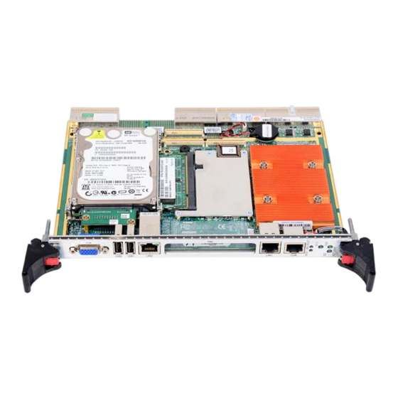
Advantech MIC-3392 User Manual (72 pages)
6U CompactPCI Intel Core 2 Duo Processor Based Board with Dual PCIe GbE/DDR2/SATA/PMC
Brand:
Advantech
| Category:
Motherboard
| Size: 1.31 MB
Table of Contents
Declaration of Conformity
3
Packing List
4
Safety Instructions
5
Table of Contents
9
Chapter 1 Hardware Configuration
13
Introduction
14
Table 1.1: MIC-3392 Variants
14
Specifications
14
Compactpci Bus Interface
14
Cpu
15
Processor
15
Table 1.2: Intel Processors
15
Bios
15
Chipset
15
Memory
16
Table 1.3: SODIMM Types (Non-ECC)
16
Ethernet
17
Storage Interface
17
Serial Ports
17
USB Port
17
Leds
17
Watchdog Timer
17
Optional Rear I/O Modules
17
Mechanical and Environmental Specifications
18
Compact Mechanical Design
18
Compactpci Bridge
18
I/O Connectivity
19
PMC (PCI Mezzanine Card) IEEE1386.1 Compliant
19
Hardware Monitor
19
Super IO
19
RTC and Battery
19
Ipmi
19
HPET and IO/APIC
20
Functional Block Diagram
20
Figure 1.1 MIC-3392 Functional Block Diagram
20
Jumpers and Switches
21
Table 1.4: MIC-3392 Jumper Descriptions
21
Table 1.5: MIC-3392 Switch Descriptions
21
Jumper Settings
21
Table 1.6: JP2 VGA Output Settings
21
Table 1.7: JP14 PMC2 V(IO) Settings
21
Table 1.8: JP4 PMC1 PCI Bus Frequency Settings
21
Clear CMOS (JP1)
22
Table 1.9: JP1 Clear CMOS
22
Switch Settings
22
Table 1.10: SW5-1 LAN for BMC
22
Table 1.11: SW5-2 SATA HDD Channel Setting (Single PMC)
22
Table 1.12: SW5-2 SATA HDD Channel Setting (Dual PMC)
22
Table 1.13: SW5-3 & SW5-4: COM2 to Console or BMC
23
Table 1.14: SW6 IPMI Programming Setting
23
Table 1.15: SW7 - Master/Drone Mode Setting
23
Table 1.16: SW1: BMC Reset Button & Platform Reset Button
23
Figure 1.2 MIC-3392 Jumper, Switch and Connector Locations
24
Connector Definitions
24
Table 1.17: MIC-3392 Connector Descriptions
24
VGA Display Connector (VCN1 or Rear I/O)
25
Serial Ports (CN9 and Rear I/O)
25
USB Connector (CN11/12 and Rear I/O)
25
Compactflash Socket (CN10)
25
SATA Daughter Board Connector (CN4) (Single PMC Only)
25
Ethernet Configuration (RJ1/RJ2 or Rear I/O RJ1)
26
PMC Connector (J23 for PMC1, Jxx for PMC2)
26
SW1 (System Reset and BMC Reset Button)
26
Safety Precautions
26
Installing the CPU and Heatsink
27
Figure 1.3 Complete Assembly of CPU and Heat Sink
27
CPU & Heatsink Installation Steps
28
Battery Replacement
29
Software Support
29
Chapter 2 AMI BIOS Setup
31
Figure 2.1 Setup Program Initial Screen
32
Introduction
32
Entering Setup
33
Figure 2.2 Press del to Run Setup
33
Main Setup
34
Figure 2.3 Main Setup Screen
34
System Time/System Date
34
Advanced BIOS Features Setup
35
Figure 2.4 Advanced BIOS Features Setup Screen
35
CPU Configuration
36
Figure 2.5 CPU Configuration
36
LAN & Smbus Configuration
37
Figure 2.6 LAN & Smbus Configuration
37
Table 2.1: Select Smbus Mode
37
IDE Configuration
38
Figure 2.7 IDE Configuration
38
Floppy Configuration
39
Figure 2.8 Floppy Configuration
39
Super I/O Configuration
40
Figure 2.9 Super I/O Configuration
40
ACPI Setting
41
Figure 2.10ACPI Setting
41
Hardware Health Configuration
41
Figure 2.11Hardware Health Configuration
41
Console Redirection Configuration
42
Figure 2.12Configure Remote Access Types and Parameters
42
PCI/PNP Setup
43
Figure 2.13PCI/PNP Setup
43
Clear NVRAM
43
Plug and Play O/S
43
PCI Latency Timer
43
Boot Setup
44
Figure 2.14Boot Setup
44
Boot Settings Configuration
44
Figure 2.15Boot Settings Configuration
44
Security Setup
45
Figure 2.16Password Configuration
45
Advanced Chipset Settings
46
Figure 2.17Advanced Chipset Setting
46
North Bridge Chipset Configuration
46
Figure 2.18North Bridge Configuration
46
South Bridge Configuration
47
Figure 2.19South Bridge Configuration
47
Exit Option
48
Figure 2.20Exit Option
48
Save Changes and Exit
48
Discard Changes and Exit
48
Load Defaults
48
Chapter 3 IPMI
49
Introduction
50
Definitions
50
IPMI Function List
50
IPMI Device Global Commands
51
Table 3.1: Supported IPMI Commands
51
BMC Device and Messaging Interfaces
51
Table 3.2: H8S12C Bus Connection to NIC Smbus
51
Table 3.3: NIC Interrupt
51
Table 3.4: BMC Device and Messaging Commands
52
BMC Watchdog Timer Commands
52
Table 3.5: BMC Watchdog Timer Commands
52
Chassis Device Commands
53
Table 3.6: Chassis Device Commands
53
Event Commands
53
Table 3.7: Event Commands
53
PEF and Alerting Commands
53
Table 3.8: PEF and Alerting Commands
53
SEL Device Commands
54
Table 3.9: SEL Device Commands
54
SDR Device Commands
54
Table 3.10: SDR Device Commands
54
FRU Data
54
Table 3.11: FRU Device Commands
54
Sensors and Threshold Configuration
55
Table 3.12: Sensor List
55
Table 3.14: Sensor Device Commands
56
Table 3.13: Threshold Values of Sensors
56
Serial over LAN
56
Table 3.15: LAN Device Commands
56
Serial/Modem Device Commands
56
Table 3.16: Serial/Modem Device Commands
56
BMC Reset
57
Appendix A Pin Assignments
59
J1 Connector
60
A.1 J1 Connector
60
Table A.1: J1 Compactpci I/O
60
J2 Connector
61
A.2 J2 Connector
61
Table A.2: J2 Compactpci I/O
61
J3 Connector
62
A.3 J3 Connector
62
Table A.3: J3 Compactpci I/O (LPT, FDD, Parallel IDE, 2.16)
62
J5 Connector
63
Other Connectors
63
A.4 J5 Connector
63
A.5 Other Connectors
63
Table A.4: J5 Compactpci I/O (VGA, LAN, COM, USB, PS/2)
63
Table A.5: VCN1 VGA Connector
63
Table A.6: CN9 COM1 (RJ45) Connector
64
Table A.7: CN4 & CN5 USB Port 1 & Port 2
64
Table A.8: BT1 CMOS Battery
64
Table A.9: CN10 CF Socket
64
Table A.10:CN4 SATA Daughter Board Connector
65
Table A.11:RJ1 LAN1 Connector
65
Table A.12:RJ1 LAN1 Indicator
65
M/D, PWR & Ide/Hot-Swap Leds
66
Appendix B Programming the Watchdog Timer
67
Watchdog Timer Programming Procedure
68
Cpld
69
Appendix C CPLD
70
Features
70
CPLD I/O Registers
70
Table C.1: LPC I/O Registers Address
70
Debug Message
70
Table C.2: Debug_Code [7:0] (LPC I/O Address: 80H)
70
Watchdog Register
70
Table C.3: Watchdog [7:0] (LPC I/O Address: 443H)
70
Watchdog Disable Register
71
Table C.4: Watchdog [7:0] (LPC I/O Address: 444H)
71
Table C.5: Version [7:0] (LPC I/O Address: 445H)
71
Geography Address (GA)
71
Table C.6: GA [7:0] (LPC I/O Address: 447H)
71
Advertisement
Advantech MIC-3392 User Manual (74 pages)
Brand:
Advantech
| Category:
Computer Hardware
| Size: 4.26 MB
Table of Contents
Table of Contents
8
Chapter 1 Hardware Configuration
12
Introduction
13
Specifications
14
Compactpci Bus Interface
14
Cpu
14
Processor
14
Bios
14
Chipset
15
Memory
15
Ethernet
16
Storage Interface
16
Serial Ports
16
USB Port
16
Leds
17
Watchdog Timer
17
Optional Rear I/O Modules
17
Mechanical and Environmental Specifications
17
Compact Mechanical Design
17
Compactpci Bridge
18
I/O Connectivity
18
PMC (PCI Mezzanine Card) IEEE1386.1 Compliant
19
Hardware Monitor
19
Super IO
19
RTC and Battery
19
Ipmi
19
HPET and IO/APIC
19
Functional Block Diagram
20
Jumpers and Switches
21
Jumper Settings
21
Clear CMOS (JP1)
22
Switch Settings
22
Connector Definitions
24
VGA Display Connector (VCN1 or Rear I/O)
25
Serial Ports (CN9 and Rear I/O)
25
USB Connector (CN11/12 and Rear I/O)
25
Compactflash Socket (CN10)
25
SATA Daughter Board Connector (CN4) (Single PMC Only)
26
Ethernet Configuration (RJ1/RJ2 or Rear I/O RJ1)
26
PMC Connector (J23 for PMC1, Jxx for PMC2)
26
SW1 (System Reset and BMC Reset Button)
26
Safety Precautions
26
Installing the CPU and Heatsink
27
CPU & Heatsink Installation Steps
28
Battery Replacement
29
Software Support
30
Chapter 2 AMI BIOS Setup
32
Introduction
33
Entering Setup
34
Main Setup
35
System Time/System Date
35
Advanced BIOS Features Setup
36
CPU Configuration
37
LAN & Smbus Configuration
38
IDE Configuration
39
Floppy Configuration
40
Super I/O Configuration
41
ACPI Setting
42
Hardware Health Configuration
42
Console Redirection Configuration
43
PCI/PNP Setup
44
Clear NVRAM
44
Plug and Play O/S
44
PCI Latency Timer
44
Boot Setup
45
Boot Settings Configuration
45
Security Setup
46
Advanced Chipset Settings
47
North Bridge Chipset Configuration
47
South Bridge Configuration
48
Exit Option
49
Save Changes and Exit
49
Discard Changes and Exit
49
Load Defaults
49
Chapter 3 IPMI
50
Introduction
51
Definitions
51
IPMI Function List
51
IPMI Device Global Commands
52
BMC Device and Messaging Interfaces
52
BMC Watchdog Timer Commands
53
Chassis Device Commands
54
Event Commands
54
PEF and Alerting Commands
54
SEL Device Commands
55
SDR Device Commands
55
FRU Data
55
Sensors and Threshold Configuration
56
Serial over LAN
57
Serial/Modem Device Commands
57
BMC Reset
58
Appendix A Pin Assignments
60
J1 Connector
61
J2 Connector
62
J3 Connector
63
J5 Connector
64
Other Connectors
64
M/D, PWR & Ide/Hot-Swap Leds
67
Appendix B Programming the Watchdog Timer
68
Watchdog Timer Programming Procedure
69
Cpld
70
Appendix C CPLD
71
Features
71
CPLD I/O Registers
71
Debug Message
71
Watchdog Register
71
Watchdog Disable Register
72
Geography Address (GA)
72
Advertisement
Related Products
Advantech MIC-3396
Advantech MIC-3397
Advantech MIC-3358
Advantech MIC-3329 Series
Advantech MIC-3329A1-D2E
Advantech MIC-3329C1-D1E
Advantech MIC-3329B1-D1E
Advantech MIC-3329R1-D1E
Advantech MIC-3329C1-D2E
Advantech MIC-3351
Advantech Categories
Motherboard
Computer Hardware
Desktop
Touch Panel
PCI Card
More Advantech Manuals
Login
Sign In
OR
Sign in with Facebook
Sign in with Google
Upload manual
Upload from disk
Upload from URL