
Related Manuals for Advantech TPC-1070


Summary of Contents for Advantech TPC-1070
-
Page 1: User Manual
TPC-1070 Intel Touch Panel Computer with High Luminance 10.4" SVGA TFT LCD User Manual... - Page 2 Acknowledgements Intel and Pentium are trademarks of Intel Corporation. Microsoft Windows and MS-DOS are registered trademarks of Microsoft Corp. All other product names or trademarks are properties of their respective owners.
- Page 3 Product Warranty (2 years) Advantech warrants to you, the original purchaser, that each of its prod- ucts will be free from defects in materials and workmanship for two years from the date of purchase. This warranty does not apply to any products which have been repaired or altered by persons other than repair personnel authorized by Advantech, or which have been subject to misuse, abuse, accident or improper instal- lation.
-
Page 4: Declaration Of Conformity
- Product name and serial number - Description of your peripheral attachments - Description of your software (operating system, version, appli- cation software, etc.) - A complete description of the problem - The exact wording of any error messages TPC-1070 User Manual... - Page 5 Safety Instructions Read these safety instructions carefully. Keep this User's Manual for later reference. Disconnect this equipment from any AC outlet before cleaning. Use a damp cloth. Do not use liquid or spray detergents for clean- ing. For plug-in equipment, the power outlet socket must be located near the equipment and must be easily accessible.
- Page 6 Beachten Sie beim. AnschluB an das Stromnetz die AnschluBw- erte. Verlegen Sie die NetzanschluBleitung so, daB niemand darüber fallen kann. Es sollte auch nichts auf der Leitung abgestellt werden. Alle Hinweise und Warnungen die sich am Geräten befinden sind zu beachten. TPC-1070 User Manual...
- Page 7 Wird das Gerät über einen längeren Zeitraum nicht benutzt, sollten Sie es vom Stromnetz trennen. Somit wird im Falle einer Überspan- nung eine Beschädigung vermieden. Durch die Lüftungsöffnungen dürfen niemals Gegenstände oder Flüssigkeiten in das Gerät gelangen. Dies könnte einen Brand bzw. elektrischen Schlag auslösen.
- Page 8 TPC-1070 User Manual viii...
-
Page 9: Table Of Contents
Advantech COM Driver ... 17 Touchscreen Driver ... 17 Watchdog Timer Driver ... 17 Installing the TPC-1070 Watchdog Timer Driver ... 27 How to Use the TPC-1070 Watchdog Timer ... 32 Version Information ... 37 OSLock and OSUnLock ... 38 Table of Contents... - Page 10 Appendix F Touchscreen Installation & Configuration. 68 Driver Installation ... 68 Uninstall the Driver... 70 Touchscreen Calibration ... 71 TPC-1070 User Manual HORM ... 38 Figure C.1:Watchdog timer programming procedure .. 53 Table C.1:Watchdog Timer Registers ... 54 Figure D.1:Adapter Board and IDE Cable ... 62 Figure D.2:Connecting Adapter Board &...
- Page 11 Appendix G Fuse Specifications ... 80 Fuse Specifications... 80 Fuse Replacement ... 80 Figure F.13:Plot Calibration Data ... 75 Figure F.14:Draw ... 76 Figure F.15:Clear Screen ... 76 Figure F.16:Option ... 77 Figure G.1:Fuse Replacement ... 80 Table of Contents...
- Page 12 TPC-1070 User Manual...
- Page 13 General Information Sections include: • Introduction • Specifications • LCD Specifications • Touchscreen Specifications • Power • I/O Ports Arrangement • Panel Mounting • Dimensions & Cutout...
-
Page 14: Chapter 1 General Information
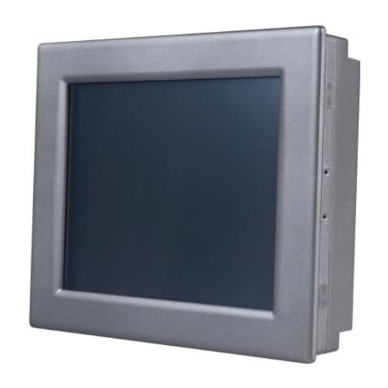
Chapter 1 General Information This chapter gives the background information about the TPC-1070. 1.1 Introduction The TPC-1070 touch panel computer is state-of-the-art HMI (Human Machine Interface). This 10.4” display operator interface is an x86-based platform with these key features: Fanless:... -
Page 15: I/O Ports
1.2.2 I/O Ports 3 serial ports: RS-232 (COM1, COM3) and RS-232/422/485 (COM4) 2 RJ-45 Ethernet port: TPC-1070H-P1E, LAN 1(10/100BaseT); LAN 2(10/100/1000BaseT) TPC-1070H-C1E, LAN 1(10/100BaseT); LAN 2(10/100BaseT) 1 PS/2 port: 6-pin mini-DIN ports for keyboard and mouse 2 USB ports: compliant with USB 2.0 1 Compact Flash Slot: TypeII 1 PCI-104 1.2.3 Safety and Environment... -
Page 16: Lcd Specifications
There might be several bright or dark pixels on the LCD. This comes from the production of the LCD. Such phenomenon is claimed to be normal accord- ing to the LCD manufacturers. TPC-1070 User Manual TFT color LCD 10.4” 800 x 600 (SVGA) 260K 0.264 x 0.264 mm... -
Page 17: Touchscreen Specifications
1.4 Touchscreen Specifications Touchscreen Type Base Glass Construction Resolution Light Transmission Controller Power Rating Durability 1.5 Power Input voltage: 18 ~ 32 Vdc (the fuse will be open circuit as input level exceeds 33Vdc) Typical: 24V@2.5A (60W) Resistive Tempered Glass 1024 x 1024 75% typical RS232 Interface... -
Page 18: I/O Port Arrangement
1.6 I/O Port Arrangement The arrangement of the I/O ports is shown in Figure 1.1. Figure 1.1: I/O port arrangement TPC-1070 User Manual... -
Page 19: Panel Mounting
1. There is a piece of adhesive waterproof gasket on the Mg-AL front bezel. Make sure the waterproof gasket is in position before installing the TPC-1070 to the panel opening. 2. Install the TPC-1070 to the panel opening. 3. Find out the eight clampers and eight long screws in the accessory pack. -
Page 20: Dimensions And Cutout
1.8 Dimensions & Cutout Weight:: 3.5 Kg (without HDD) Dimensions: 286 x 226 x 58mm (WxHxD) Cutout: 279.5 x 219.5 mm (suggested) TPC-1070 User Manual Figure 1.3: Dimensions... - Page 21 System Setup...
-
Page 22: Figure 2.1:Install Compactflash Memory Card
Chapter 2 System Setup This chapter provides a brief explanation for operating the TPC-1070. It is easy to make the TPC-1070 start working with the below step-by-step. Step 1: Unpack the TPC-1070 package. Please check the packing list at the beginning of this manual. -
Page 23: Figure 2.3:Power Receptor And Button Pin Assignments
Figure 2.3: Power receptor and button pin assignments Step 4: Plug the power lines to the system power receptor. Step 5: Push the power button to power on the system as the figure 2.4. Step 6: Calibrate the touchscreen. Please go to: “Start”... -
Page 24: Figure 2.4:Touchscreen Calibration - 1
Figure 2.4: Touchscreen Calibration - 1 Figure 2.5: Touchscreen Calibration - 2 TPC-1070 User Manual... - Page 25 System Engine...
-
Page 26: Figure 3.1:Main Board Connector
COM4 MODE1 COM4 MODE2 IRQ selection Buzzer POWER SWITCH Address selection Figure 3.1: Main Board Connector TPC-1070 User Manual Description Internal 18bit LVDS LCD Connector LCD INVERTER Connector Internal Touch screen Connector PCI-104 IDE connector for 40pin 2.5îinternal HDD DC Power in Connector, HOUSING 5.08 MM 3P Two USB Type-A Female to on panel. - Page 27 Software Configuration Sections include: • Utilities & Drivers • Advantech COM Driver Installation • Watchdog Timer Driver Installation...
-
Page 28: Chapter 4 Software Configuration
Chapter 4 Software Configuration A support CD-ROM for TPC-1070 is available and along with the prod- uct. There are related utilities and drivers for TPC-1070 included. Please install the Chipset INF driver, VGA graphics driver, LAN driver, audio driver, Advantech.com driver, Touchscreen driver and Watchdog Timer (WDT) driver sequentially. -
Page 29: Advantech Com Driver
4.1.4 Advantech COM Driver Path: \TPC-1070H\Driver\Advantech COM\ Available for the OS’s below: • Microsoft Windows 2000 • Microsoft Windows XP 4.1.5 Touchscreen Driver Path: \TPC-1070H\Driver\PenMount\ Available for the OS’s below: • Microsoft Windows 2000 • Microsoft Windows XP 4.1.6 Watchdog Timer Driver Path: \TPC-1070H\Driver\WDT\8362x Available for the OS’s below: •... -
Page 30: Advantech Com Driver Installation
4.2 Advantech COM Driver Installation A com port named COM3 or COM4 on TPC-1070 is Advantech Special com port. Please follow the steps below to install the driver. Step 1: Insert the companion CD-ROM into your CD-ROM drive. Open the directory: \TPC-1070H\Driver\Advantech COM\ Step 2: Use Windows Explorer (or Windows Run command) to execute PCI_ICOM.EXE from the companion CD-ROM. - Page 31 Step 3: Click Next to continue installation. Step 4: Click Next to continue installation. Chapter 4...
- Page 32 Step 5: Click uninstall icon to remove ?PCI Serial Port TPC-1070 User Manual...
- Page 33 Step 6: Click the scan for hardware changes icon to remove ?PCI Serial Port Chapter 4...
- Page 34 Step 7: Found New Hardware and Click Next to continue installation. TPC-1070 User Manual...
- Page 35 Step 8: Click Finish the Advantech PCI Serial Port to continue. Step 9: Then, found New Hardware and Click Next to continue. Chapter 4...
- Page 36 Step 10: Click Finish the Advantech PCI-1602 Serial SlaveBridge to continue installation. TPC-1070 User Manual...
- Page 37 Step 11: Found New Hardware and Click Next to continue installation. Step 12: Click Finish the Advantech PCI Serial Port to continue. Chapter 4...
-
Page 38: Watchdog Timer (Wdt) Driver Installation
4.3 Watchdog Timer (WDT) Driver Installation In order to ensure reliable and fail-safe performance, TPC-1070 has a built-in Watchdog Timer to handle unexpected system failures. TPC- 1070 provides the drivers and a utility to activate and configure the timer for Windows2000/XP operating systems. The following is a brief intro- duction, using Windows2000 as an example, for the installation and con- figuration procedures. -
Page 39: Installing The Tpc-1070 Watchdog Timer Driver
4.3.1 Installing the TPC-1070 Watchdog Timer Driver Step 1: Insert the companion CD-ROM into your CD-ROM drive. Open the directory: \WDT\8362x\W2K_XP. Step 2: Use Windows Explorer (or Windows Run command) to execute SETUP.EXE from the companion CD-ROM. Chapter 4... - Page 40 Step 3: Click Next to proceed. TPC-1070 User Manual...
- Page 41 Step 4: Click Next to confirm the customer information. Step 5: Select Advantech [W83627HF] Watchdog Timer and click Next. Chapter 4...
- Page 42 Step 6: Click Next to confirm selecting the Typical setup type. Step 7: Click Next to proceed. TPC-1070 User Manual...
- Page 43 Step 8: Click Finish to complete the procedure. Step 9: Click OK to restart the system and activate the Watchdog Timer. Chapter 4...
-
Page 44: How To Use The Tpc-1070 Watchdog Timer
4.3.2 How to Use the TPC-1070 Watchdog Timer Step 1: Open the Control Panel, click Watchdog Service Configuration. Step 2: Click the Start Service button. TPC-1070 User Manual... - Page 45 Step 3: Click Setting to select the setting page. Step 4: Select the Timer Span that meets your application requirement. Chapter 4...
- Page 46 Step 6: Check the Start watchdog service on boot to enable the Watchdog timer to start automatically after the system boots every time. Step 7: Click OK, then the configuration procedure is finished. Note TPC-1070 User Manual Use Advantech WDT Driver.WDT was enable,and WDT LED was 1Hz glisten.
- Page 47 Windows XP Embedded Sections include: • EWF • HORM • Advantech Utilities...
-
Page 48: Chapter 5 Windows Xp Embedded
Chapter 5 Windows XP Embedded TPC-1070 is in support of embedded windows platform. This section is to state the important features, EWF and HORN, provided in windows XP embedded. 5.1 EWF EWF stands for Enhanced Write Filter. It provides an upper filter in the storage device driver stack that redirects disk write operations to volatile (RAM) or non-volatile (disk) storage. -
Page 49: Advantech Utilities
In other words, the hibernation file is 512MB that is the same as memory size used on TPC-1070H-P1E or TPC-1070H-C1E. 5.3 Advantech Utilities TPC-1070 provides the useful utilities for users to configure the HORM and EWF. 5.3.1 Version Information Start menu->... -
Page 50: Oslock And Osunlock
Please follow the steps before running this utility to create full HORM environment. Enable Hibernation via Power Options in Control Panel Make C: partition EWF-enabled via OSLock Make sure that all volumes to be dismounted are not in use. TPC-1070 User Manual... - Page 51 Serial Port Settings...
-
Page 52: A.2 Com4 Setting
A.1 COM1/ COM3 Connector Definition A.2 COM4 Setting The serial port COM4 on the TPC-1070 is adjustable. It can be set to RS- 232, RS-422 or RS-485. This port is designed with auto data flow control capability. In other word, the TPC-1070 can automatically detect the data flow direction at this port when the two wired RS-485 communication is activated. - Page 53 Note: indicates the switch jumper 0 9 8 7 6 5 4 3 2 1 0 9 8 7 6 5 4 3 0 9 8 7 6 5 4 3 2 RS-232 NDCD NDTR NDSR NRTS NCTS RS232 RS485 RS422-MASTER RS422-SLAVE RS-422...
- Page 54 TPC-1070 User Manual...
- Page 55 Watchdog Timer on WinCE 5.0...
-
Page 56: B.1 Deviceiocontrol
Appendix B Watchdog Timer on WinCE There is a built-in Watchdog timer on Windows CE 5.0 for TPC-1070. You can access it through WIN32 API. TPC-1070 provides a WDT driver to allow users to enable/disable the Watchdog timer. The driver name is “WDT1:”. - Page 57 control codes can then be advertised, and an application can use these control codes with DeviceIoControl to perform driverspecific functions. lpInBuffer [in] Long pointer to a buffer that contains the data required to perform the operation. This parameter can be NULL if the dwIoControlCode parame- ter specifies an operation that does not require input data.
-
Page 58: How To Use The Control Code
WDT driver, your application must trigger the Watchdog once during the Watchdog timer period. If your application has not triggered at the specified period, the device will reboot automatically. lpInBuffer: unused. nInBufferSize: unused. lpOutBuffer: unused. nOutBufferSize: unused. TPC-1070 User Manual... - Page 59 IOCTL_WDT_GETTIMEOUT: Gets the Watchdog time setting. lpInBuffer: unused. nInBufferSize: unused. lpOutBuffer: The DWORD pointer to your Watchdog time setting. The Watchdog time setting is just a number. 0 means 2 seconds, 1 means 5 seconds, 2 means 10 seconds, 3 means 15 seconds, 4 means 30 seconds, 5 means 45 seconds and 6 means 60 seconds.
-
Page 60: B.3 Examples
// assign the WDT driver name wsprintf(szClassName, TEXT("WDT1:")); // Open the WDT driver m_hWDT = CreateFile(szClassName, GENERIC_READ GENERIC_WRITE, 0, NULL, OPEN_EXISTING, FILE_ATTRIBUTE_NORMAL, NULL); if ( m_hWDT == INVALID_HANDLE_VALUE ) { DebugMsg(CString("WDT driver fail")); return; DWORD dwTemp; DWORD nIndex=2; TPC-1070 User Manual... - Page 61 // Set the Watchdog Timer as 10 seconds. Number 2 means 10 seconds. DeviceIoControl(m_hWDT, IOCTL_WDT_SET_TIMEOUT, &nIndex, sizeof(nIndex), NULL, 0, &dwTemp, NULL); // Enable the Watchdog timer DeviceIoControl(m_hWDT, IOCTL_WDT_ENABLE, NULL, 0, NULL, 0, &dwTemp, NULL); While (1) { // do your job here. Sleep(8000);...
- Page 62 TPC-1070 User Manual...
- Page 63 Watchdog Timer Programming...
-
Page 64: C.1 Overview
Appendix C Watchdog Timer C.1 Overview The TPC-1070 cards’ watchdog timer can be used to monitor system soft- ware operation and take corrective action if the software fails to function after the programmed period. This section describes the operation of the watchdog timer, and how to program it. -
Page 65: Figure C.1:Watchdog Timer Programming Procedure
C.2 Watchdog Timer Programming The I/O port address of the watchdog timer is 2E(hex) and 2F(hex), 2E (hex) is the address port. 2F(hex) is the data port. You must first assign the address of register by writing address value into address port 2E(hex), then write/read data to/from the assigned register through data port 2F (hex). -
Page 66: Table C.1:Watchdog Timer Registers
F5 (hex) Write 0 to bit 3: set second as counting unit. [default] Write 1 to bit 3: set minute as counting unit F6 (hex) F7 (hex) AA (hex) TPC-1070 User Manual Attribute Description Value (2F) description ----- Write this address to I/O address... -
Page 67: C.3 Example Programs
C.3 Example Programs 1. Enable watchdog timer and set 10 sec. as timeout interval ;----------------------------------------------------------- Mov dx,2eh ; Unlock W83627HF Mov al,87h Out dx,al Out dx,al ;----------------------------------------------------------- Mov al,07h ; Select registers of watchdog timer Out dx,al Inc dx Mov al,08h Out dx,al ;----------------------------------------------------------- Dec dx ;... - Page 68 Inc dx Mov al,08h Out dx,al ;----------------------------------------------------------- Dec dx ; Enable the function of watchdog timer Mov al,30h Out dx,al Inc dx Mov al,01h Out dx,al ;----------------------------------------------------------- Dec dx ; Set minute as counting unit Mov al,0f5h TPC-1070 User Manual...
- Page 69 Out dx,al Inc dx In al,dx Or al,08h Out dx,al ;----------------------------------------------------------- Dec dx ; Set timeout interval as 5 minutes and start counting Mov al,0f6h Out dx,al Inc dx Mov al,5 Out dx,al ;----------------------------------------------------------- Dec dx ; lock W83627HF Mov al,0aah Out dx,al 3.
- Page 70 4. Enable watchdog timer to be reset by keyboard ;----------------------------------------------------------- Mov dx,2eh ; unlock W83627H Mov al,87h Out dx,al Out dx,al ;----------------------------------------------------------- Mov al,07h ; Select registers of watchdog timer Out dx,al Inc dx Mov al,08h Out dx,al ;----------------------------------------------------------- TPC-1070 User Manual...
- Page 71 Dec dx ; Enable the function of watchdog timer Mov al,30h Out dx,al Inc dx Mov al,01h Out dx,al ;----------------------------------------------------------- Dec dx ; Enable watchdog timer to be strobed reset by keyboard Mov al,0f7h Out dx,al Inc dx In al,dx Or al,40h Out dx,al ;-----------------------------------------------------------...
- Page 72 Dec dx ; Generate a time-out signal Mov al,0f7h Out dx,al ;Write 1 to bit 5 of F7 register Inc dx In al,dx Or al,20h Out dx,al ;----------------------------------------------------------- Dec dx ; lock W83627HF Mov al,0aah Out dx,al TPC-1070 User Manual...
-
Page 73: Accessory Kit
Accessory Kit Assembly This appendix shows how to connect to a CD-ROM via the CompactFlash slot.:... -
Page 74: Figure D.2:Connecting Adapter Board & Ide Cable
Please follow this assembly procedure to use the CompactFlash slot to connect with a CD-ROM drive. Connect the IDE cable to the adapter board. Figure D.1: Adapter Board and IDE Cable Figure D.2: Connecting Adapter Board & IDE Cable TPC-1070 User Manual... -
Page 75: Figure D.4:Insert The Adapter Board Into The Cf Slot
Note Pin 1 is marked red Insert the adapter board into the CompactFlash slot. Figure D.3: CompactFlash Slot Figure D.4: Insert the Adapter Board into the CF slot Figure D.5: Inserted Adapter Board Appendix D... -
Page 76: Figure D.6:Connect The Cd-Rom Via The Ide Cable
Note Please make sure Windows 2000 Service Pack 4 is installed before you install the USB 2.0 driver on Windows 2000. Service Pack 1 must be installed on Windows XP before you install the USB 2.0 driver. TPC-1070 User Manual... - Page 77 HDD Kit Assembly...
-
Page 78: Figure E.1:Removing The Rear Hdd Cover
Deassemble the HDD kit from the system and remove the screws. Figure E.2: Removing the Top Screws Put the HDD into the HDD holder and fasten the screws and the HDD bracket.. TPC-1070 User Manual Figure E.3: Installing the HDD... - Page 79 Touchscreen Installation & Configuration This appedix demonstrates how to install the PenMount 9000 touchscreen and set the configuration on TPC- 1260H. This section uses Windows XP as an example.
-
Page 80: F.1 Driver Installation
Configuration F.1 Driver Installation Please insert the x86 TPC series support CD and go to the Windows 2000-XP driver folder (TPC-1070\Driver\Touch Screen\Driver\Windows 2000-XP Driver V4.01). Click setup.exe The screen displays the installation wizard for the PenMount software. Click “Next”. Follow the installation wizard step by step. -
Page 81: Figure F.3:Install – License Agreement
Figure F.3: Install – License Agreement Figure F.4: Install – Completed Appendix F... -
Page 82: Figure F.5:Uninstall -1
F.2 Uninstall the Driver Please go to Settings and then select Control Panel. Please click Add/ Remove Programs. Select PenMount DMC9000 and DMC9100. Click Remove button. TPC-1070 User Manual Figure F.5: Uninstall -1 Figure F.6: Uninstall -2... -
Page 83: F.3 Touchscreen Calibration
Mount Control Panel. It contains six functions: Calibrate, Draw, Multiple Monitors, Option, and About. Multiple Monitors is for multiple displays only; however TPC-1070 only provides one touchscreen display. This function is not workable on TPC-1070. About is to show the driver ver- sion. Calibrate Two ways to calibrate the touch screen include “Standard Calibration”... -
Page 84: Figure F.8:Standard Calibration -1
Figure F.8: Standard Calibration -1 Figure F.9: Standard Calibration -2 TPC-1070 User Manual... -
Page 85: Figure F.10:Standard Calibration -3
Figure F.10: Standard Calibration -3 Note Touch the red squares in sequence. The cali- bration is completed after the fifth touch red point is calibrated. Press “ESC” to skip. Advanced Calibration is for the aged touchscreens by using 4, 9, 16 or 25 points to calibrate touch panel. -
Page 86: Figure F.11:Advanced Calibration -1
Figure F.11: Advanced Calibration -1 Figure F.12: Advanced Calibration -2 TPC-1070 User Manual... -
Page 87: Figure F.13:Plot Calibration Data
Figure F.13: Plot Calibration Data Note Plot Calibration Data enabled provides the blue lines to show linearity before calibration and black lines to show linearity after calibration when you finished the advanced calibration. Draw This is to test the touch screen operation. Its display shows touch loca- tion. -
Page 88: Figure F.15:Clear Screen
Figure F.14: Draw Click “menu” and then click “clear screen” to clear the drawing. Figure F.15: Clear Screen TPC-1070 User Manual... -
Page 89: Figure F.16:Option
Option This option is to set the operation mode and beep sounds if the beep sound is enabled. The operation mode, stream mode and point mode, is to enable/ disable the mouse’s ability to drag on-screen icons. Stream mode let the mouse functions as normal and dragging on-screen. Point mode is only let the mouse a click function. - Page 90 TPC-1070 User Manual...
- Page 91 Fuse Specifications...
-
Page 92: G.1 Fuse Specifications
Warning Do NOT replace the fuse unless it is damaged. Do NOT replace the fuse with a different rating. TPC-1070 User Manual The fuse is set to break as the input voltage exceeds 33VDC for your protection. Figure G.1: Fuse Replacement...
Need help?
Do you have a question about the TPC-1070 and is the answer not in the manual?
Questions and answers