
Related Manuals for Advantech TPC-1270


Summary of Contents for Advantech TPC-1270
-
Page 1: User Manual
TPC-1270 Intel Touch Panel Computer with High Luminance 12.1" SVGA TFT LCD User Manual... - Page 2 No part of this man- ual may be reproduced, copied, translated or transmitted in any form or by any means without the prior written permission of Advantech Co., Ltd. Information provided in this manual is intended to be accurate and reli- able.
- Page 3 Product Warranty (2 years) Advantech warrants to you, the original purchaser, that each of its prod- ucts will be free from defects in materials and workmanship for two years from the date of purchase. This warranty does not apply to any products which have been repaired or...
-
Page 4: Declaration Of Conformity
This product has passed the CE test for environmental specifications when shielded cables are used for external wiring. We recommend the use of shielded cables. This kind of cable is available from Advantech. Please contact your local supplier for ordering information. - Page 5 Safety Instructions Read these safety instructions carefully. Keep this User's Manual for later reference. Disconnect this equipment from any AC outlet before cleaning. Use a damp cloth. Do not use liquid or spray detergents for clean- ing. For plug-in equipment, the power outlet socket must be located near the equipment and must be easily accessible.
- Page 6 The sound pressure level at the operator's position according to IEC 704- 1:1982 is no more than 70 dB (A). DISCLAIMER: This set of instructions is given according to IEC 704-1. Advantech disclaims all responsibility for the accuracy of any statements contained herein. Wichtige Sicherheishinweise 1.
- Page 7 Entsorgen Sie Batterien nach Anweisung des Herstell- ers. Der arbeitsplatzbezogene Schalldruckpegel nach DIN 45 635 Teil 1000 beträgt 70dB(A) oder weiger. Haftungsausschluss: Die Bedienungsanleitungen wurden entsprechend der IEC-704-1 erstellt. Advantech lehnt jegliche Verantwortung für die Richtigkeit der in diesem Zusammenhang getätigten Aussagen ab.
- Page 8 TPC-1270 User Manual viii...
-
Page 9: Table Of Contents
Advantech COM Driver Installation ....... 19 Watchdog Timer (WDT) Driver Installation ....28 4.3.1 Installing the TPC-1270 Watchdog Timer Driver ..29 4.3.2 How to Use the TPC-1270 Watchdog Timer ....34 Chapter 5 Windows XP Embedded ....... 38 EWF ................38 HORM................38 Advantech Utilities............ - Page 10 Figure E.12:Plot Calibration Data ....... 70 Figure E.13:Draw ............71 Figure E.14:Clear Screen ..........72 Figure E.15:Option ............. 73 Appendix F Fuse Specifications ........76 Fuse Specifications............76 Fuse Replacement ............76 Figure F.1:Fuse Replacement ........76 TPC-1270 User Manual...
- Page 11 General Information Sections include: • Introduction • Specifications • LCD Specifications • Touchscreen Specifications • Power • I/O Ports Arrangement • Panel Mounting • Dimensions & Cutout...
-
Page 12: Chapter 1 General Information
The IO interface includes serial ports, RS-485 port, Ethernet and USB 2.0 support. Embedded Windows Support: In addition to the OS support of Windows XP, Advantech offers platform support for XP embedded. 1.2 Specifications 1.2.1 System Kernel CPU: Intel Pentium M, Celeron M (clock rate 1.4GHz/ 1GHz) -
Page 13: I/O Ports
1.2.2 I/O Ports 4 Serial Ports: RS-232 (COM1, COM2, COM3) and RS-232/422/485 (COM4) 2 RJ-45 Ethernet port: TPC-1270H-P1E, LAN 1(10/100BaseT); LAN 2(10/100/1000BaseT) TPC-1270H-C1E, LAN 1(10/100BaseT); LAN 2(10/100BaseT) 4 USB Ports: Compliant with USB 2.0 1 CompactFlash Slot: TypeII 1 PCI-104 1 VGA 2 Audio Ports: 1 MIC-in, 1 Line-out 1.2.3 Safety and Environment... -
Page 14: Lcd Specifications
50,000 hours Backlight Life Time Note There might be several bright or dark pixels on the LCD. This comes from the production of the LCD. Such phenomenon is claimed to be normal accord- ing to the LCD manufacturers. TPC-1270 User Manual... -
Page 15: Touchscreen Specifications
1.4 Touchscreen Specifications Resistive Touchscreen Type Tempered Glass Base Glass Construction 1024 x 1024 Resolution 80% typical Light Transmission USB Interface Controller 3.3 to 5V Power Rating 1 million touches Durability 1.5 Power Input voltage: 18 ~ 32 Vdc (the fuse will be open circuit as input level exceeds 33Vdc) Typical: 24V@2.5A (60W) Chapter 1... -
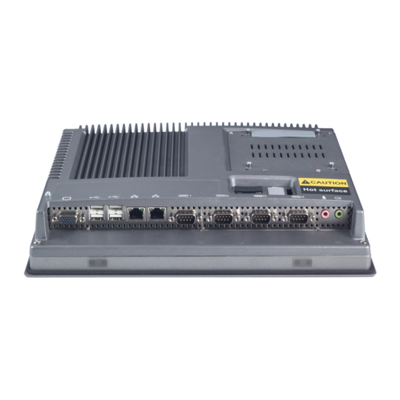
Page 16: I/O Port Arrangement
1.6 I/O Port Arrangement The arrangement of the I/O ports is shown in Figure 1.1. Figure 1.1: I/O port arrangement TPC-1270 User Manual... -
Page 17: Panel Mounting
1. There is a piece of adhesive waterproof gasket on the Mg-AL front bezel. Make sure the waterproof gasket is in position before installing the TPC-1270 to the panel opening. 2. Install the TPC-1270 to the panel opening. 3. Find out the eight clampers and eight long screws in the accessory pack. -
Page 18: Dimensions & Cutout
1.8 Dimensions & Cutout Weight:: 3.5 Kg (without HDD) Dimensions: 311 x 237 x 65 mm (WxHxD) Cutout: 312.5 x 228.5 mm (suggested) Figure 1.3: Dimensions TPC-1270 User Manual... - Page 19 System Setup...
-
Page 20: Chapter 2 System Setup
Chapter 2 System Setup This chapter provides a brief explanation for operating the TPC-1270. It is easy to make the TPC-1270 start working with the below step-by-step. Step 1: Unpack the TPC-1270 package. Please check the packing list at the beginning of this manual. -
Page 21: Figure 2.3:Power Receptor And Button Pin Assignments
Figure 2.3: Power receptor and button pin assignments Step 4: Plug the power lines to the system power receptor. Step 5: Push the power button to power on the system as the figure 2.4. Step 6: Calibrate the touchscreen. Please go to: “Start”... - Page 22 TPC-1270 User Manual...
- Page 23 I/O Connectors & Setting Mode...
-
Page 24: Chapter 3 I/O Connector & Setting Mode
COM4 MODE1 Setting COM4 RS232/422/485 mode COM4 MODE2 Setting COM4 RS422 Master or Slave mode SATA-PWR D-Sub 25-pin (Female) on panel. SATA Internal IDE 44pin(2mm) connector POWER System Power Switch SWITCH BIOS BIOS flash socket FUSE FUSE Holder TPC-1270 User Manual... - Page 25 Chapter 3...
- Page 26 TPC-1270 User Manual...
- Page 27 Software Configuration Sections include: • Utilities & Drivers • Advantech COM Driver Installation • Watchdog Timer Driver Installation...
-
Page 28: Chapter 4 Software Configuration
Chapter 4 Software Configuration A support CD-ROM for TPC-1270 is available and along with the prod- uct. There are related utilities and drivers for TPC-1270 included. Please install the Chipset INF driver, VGA graphics driver, LAN driver, audio driver, Advantech.com driver, Touchscreen driver and Watchdog Timer (WDT) driver sequentially. -
Page 29: Touchscreen Driver
Available for the OS’s below: • Microsoft Windows XP 4.2 Advantech COM Driver Installation A com port named COM2, COM3 or COM4 on TPC-1270 is Advantech Special com port. Please follow the steps below to install the driver. Chapter 4... - Page 30 Step 1: Insert the companion CD-ROM into your CD-ROM drive. Open the directory: \TPC-1270H\Driver\Advantech COM\ Step 2: Use Windows Explorer (or Windows Run command) to execute PCI_ICOM.EXE from the companion CD-ROM. Step 3: Click Next to continue installation. TPC-1270 User Manual...
- Page 31 Step 4: Click Next to continue installation. Chapter 4...
- Page 32 Step 5: Click uninstall icon to remove ?PCI Serial Port TPC-1270 User Manual...
- Page 33 Step 6: Click the scan for hardware changes icon to remove ?PCI Serial Port Chapter 4...
- Page 34 Step 7: Found New Hardware and Click Next to continue installation. TPC-1270 User Manual...
- Page 35 Step 8: Click Finish the Advantech PCI Serial Port to continue. Step 9: Then, found New Hardware and Click Next to continue. Chapter 4...
- Page 36 Step 10: Click Finish the Advantech PCI-1602 Serial SlaveBridge to continue installation. TPC-1270 User Manual...
- Page 37 Step 11: Found New Hardware and Click Next to continue installation. Step 12: Click Finish the Advantech PCI Serial Port to continue. Chapter 4...
-
Page 38: Watchdog Timer (Wdt) Driver Installation
4.3 Watchdog Timer (WDT) Driver Installation In order to ensure reliable and fail-safe performance, TPC-1270 has a built-in Watchdog Timer to handle unexpected system failures. TPC- 1270 provides the drivers and a utility to activate and configure the timer for Windows XP operating systems. The following is a brief introduction, using XP as an example, for the installation and configuration proce- dures. -
Page 39: Installing The Tpc-1270 Watchdog Timer Driver
4.3.1 Installing the TPC-1270 Watchdog Timer Driver Step 1: Insert the companion CD-ROM into your CD-ROM drive. Open the directory: \WDT\8362x\W2K_XP. Step 2: Use Windows Explorer (or Windows Run command) to execute SETUP.EXE from the companion CD-ROM. Chapter 4... - Page 40 Step 3: Click Next to proceed. TPC-1270 User Manual...
- Page 41 Step 4: Click Next to confirm the customer information. Step 5: Select Advantech [W83627HF] Watchdog Timer and click Next. Chapter 4...
- Page 42 Step 6: Click Next to confirm selecting the Typical setup type. Step 7: Click Next to proceed. TPC-1270 User Manual...
- Page 43 Step 8: Click Finish to complete the procedure. Step 9: Click OK to restart the system and activate the Watchdog Timer. Chapter 4...
-
Page 44: How To Use The Tpc-1270 Watchdog Timer
4.3.2 How to Use the TPC-1270 Watchdog Timer Step 1: Open the Control Panel, click Watchdog Service Configuration. Step 2: Click the Start Service button. TPC-1270 User Manual... - Page 45 Step 3: Click Setting to select the setting page. Step 4: Select the Timer Span that meets your application requirement. Chapter 4...
- Page 46 Step 6: Check the Start watchdog service on boot to enable the Watchdog timer to start automatically after the system boots every time. Step 7: Click OK, then the configuration procedure is finished. Note Use Advantech WDT Driver.WDT was enable,and WDT LED was 1Hz glisten. TPC-1270 User Manual...
- Page 47 Windows XP Embedded Sections include: • EWF • HORM • Advantech Utilities...
-
Page 48: Chapter 5 Windows Xp Embedded
Chapter 5 Windows XP Embedded TPC-1270 is in support of embedded windows platform. This section is to state the important features, EWF and HORN, provided in windows XP embedded. 5.1 EWF EWF stands for Enhanced Write Filter. It provides an upper filter in the storage device driver stack that redirects disk write operations to volatile (RAM) or non-volatile (disk) storage. -
Page 49: Advantech Utilities
In other words, the hibernation file is 512MB that is the same as memory size used on TPC-1270H-P1E or TPC-1270H-C1E. 5.3 Advantech Utilities TPC-1270 provides the useful utilities for users to configure the HORM and EWF. 5.3.1 Version Information Start menu->... -
Page 50: Oslock And Osunlock
5.3.2 OSLock and OSUnLock The two utilities assist users to enable or disable EWF. Please go to Start Menu-> All Programs-> Advantech. The default setting of EWF is dis- abled. Users can protect C partition from any disk writing via OSLock that is to enable EWF RAM REG Mode. - Page 51 Serial Port Settings...
-
Page 52: Appendix A Serial Port Settings
NCTS A.2 COM4 Setting The serial port COM4 on the TPC-1270 is adjustable. It can be set to RS- 232, RS-422 or RS-485. This port is designed with auto data flow control capability. In other word, the TPC-1270 can automatically detect the data flow direction at this port when the two wired RS-485 communication is activated. - Page 53 COM4 Mode S1 and S2 setting RS232 Mode RS485 Mode RS422 Master Mode RS422 Slave Mode Appendix A...
- Page 54 TPC-1270 User Manual...
- Page 55 Watchdog Timer Programming...
-
Page 56: B.1 Overview
Appendix B WDT Programming B.1 Overview The TPC-1270 cards’ watchdog timer can be used to monitor system soft- ware operation and take corrective action if the software fails to function after the programmed period. This section describes the operation of the watchdog timer, and how to program it. -
Page 57: Watchdog Timer Programming
B.2 Watchdog Timer Programming The I/O port address of the watchdog timer is 2E(hex) and 2F(hex), 2E (hex) is the address port. 2F(hex) is the data port. You must first assign the address of register by writing address value into address port 2E(hex), then write/read data to/from the assigned register through data port 2F (hex). -
Page 58: Table B.1:Watchdog Timer Registers
0. [default=0] Bit 4: Read status of watchdog timer, 1 means timer is "time out". AA (hex) ----- Write this address to I/O port 2E (hex) to lock the watchdog timer.2 TPC-1270 User Manual... -
Page 59: Example Programs
B.3 Example Programs 1. Enable watchdog timer and set 10 sec. as timeout interval ;----------------------------------------------------------- Mov dx,2eh ; Unlock W83627HF Mov al,87h Out dx,al Out dx,al ;----------------------------------------------------------- Mov al,07h ; Select registers of watchdog timer Out dx,al Inc dx Mov al,08h Out dx,al ;----------------------------------------------------------- Dec dx ;... - Page 60 Inc dx Mov al,08h Out dx,al ;----------------------------------------------------------- Dec dx ; Enable the function of watchdog timer Mov al,30h Out dx,al Inc dx Mov al,01h Out dx,al ;----------------------------------------------------------- Dec dx ; Set minute as counting unit Mov al,0f5h TPC-1270 User Manual...
- Page 61 Out dx,al Inc dx In al,dx Or al,08h Out dx,al ;----------------------------------------------------------- Dec dx ; Set timeout interval as 5 minutes and start counting Mov al,0f6h Out dx,al Inc dx Mov al,5 Out dx,al ;----------------------------------------------------------- Dec dx ; lock W83627HF Mov al,0aah Out dx,al 3.
- Page 62 4. Enable watchdog timer to be reset by keyboard ;----------------------------------------------------------- Mov dx,2eh ; unlock W83627H Mov al,87h Out dx,al Out dx,al ;----------------------------------------------------------- Mov al,07h ; Select registers of watchdog timer Out dx,al Inc dx Mov al,08h Out dx,al ;----------------------------------------------------------- TPC-1270 User Manual...
- Page 63 Dec dx ; Enable the function of watchdog timer Mov al,30h Out dx,al Inc dx Mov al,01h Out dx,al ;----------------------------------------------------------- Dec dx ; Enable watchdog timer to be strobed reset by keyboard Mov al,0f7h Out dx,al Inc dx In al,dx Or al,40h Out dx,al ;-----------------------------------------------------------...
- Page 64 Dec dx ; Generate a time-out signal Mov al,0f7h Out dx,al ;Write 1 to bit 5 of F7 register Inc dx In al,dx Or al,20h Out dx,al ;----------------------------------------------------------- Dec dx ; lock W83627HF Mov al,0aah Out dx,al TPC-1270 User Manual...
-
Page 65: Accessory Kit
Accessory Kit Assembly This appendix shows how to connect to a CD-ROM via the CompactFlash slot.:... -
Page 66: Appendix C Accessory Kit Assembly
Please follow this assembly procedure to use the CompactFlash slot to connect with a CD-ROM drive. Connect the IDE cable to the adapter board. Figure C.1: Adapter Board and IDE Cable Figure C.2: Connecting Adapter Board & IDE Cable TPC-1270 User Manual... -
Page 67: Figure C.3:Compactflash Slot
Note Pin 1 is marked red Insert the adapter board into the CompactFlash slot. Figure C.3: CompactFlash Slot Figure C.4: Insert the Adapter Board into the CF slot Figure C.5: Inserted Adapter Board Appendix C... -
Page 68: Figure C.6:Connect The Cd-Rom Via The Ide Cable
It is required to install the service pack if you want to install the USB 2.0 driver on Windows XP Note Service Pack 1 must be installed on Windows XP before you install the USB 2.0 driver. TPC-1270 User Manual... - Page 69 HDD Kit Assembly...
-
Page 70: Figure D.1:Removing The Rear Hdd Cover
Please follow the assembly procedure to install the HDD into the system. Remove the rear HDD cover. Figure D.1: Removing the Rear HDD Cover Deassemble the HDD kit from the system. Figure D.2: Removing the Top Screws TPC-1270 User Manual... -
Page 71: Figure D.3:Installing The Hdd
Put the HDD into the HDD bracket and fasten the screws.. Figure D.3: Installing the HDD Put the HDD bracket into the HDD holder. Figure D.4: Installing the HDD Bracket Appendix D... - Page 72 TPC-1270 User Manual...
- Page 73 Touchscreen Installation & Configuration This appedix demonstrates how to install the PenMount 9000 touchscreen and set the configuration on TPC-1260. This section uses Windows XP as an example.
-
Page 74: Appendix E Touchscreen Installation & Configuration
Appendix E Touchscreen Installation & Configuration E.1 Driver Installation Please insert the x86 TPC series support CD and go to the Windows 2000-XP driver folder (TPC-1270\Driver\Touch Screen\Driver\USB touchscreen). Click setup.exe Figure E.1: Setup.exe The screen displays the installation wizard for the PenMount software. -
Page 75: Figure E.3:Install – License Agreement
Figure E.3: Install – License Agreement Figure E.4: Install – Completed Appendix E... -
Page 76: Uninstall The Driver
E.2 Uninstall the Driver Please go to Settings and then select Control Panel. Please click Add/ Remove Programs. Figure E.5: Uninstall -1 Select PenMount USB. Click Remove button. Figure E.6: Uninstall -2 TPC-1270 User Manual... -
Page 77: Touchscreen Calibration
Mount Control Panel. It contains six functions: Calibrate, Draw, Multiple Monitors, Option, and About. Multiple Monitors is for multiple displays only; however TPC-1270 only provides one touchscreen display. This function is not workable on TPC-1270. About is to show the driver ver- sion. Calibrate Two ways to calibrate the touch screen include “Standard Calibration”... -
Page 78: Figure E.8:Standard Calibration -2
Figure E.8: Standard Calibration -2 Figure E.9: Standard Calibration -3 TPC-1270 User Manual... -
Page 79: Figure E.10:Advanced Calibration -1
Note Touch the red squares in sequence. The cali- bration is completed after the fifth touch red point is calibrated. Press “ESC” to skip. Advanced Calibration is for the aged touchscreens by using 4, 9, 16 or 25 points to calibrate touch panel. Figure E.10: Advanced Calibration -1 Appendix E... -
Page 80: Figure E.11:Advanced Calibration -2
Figure E.11: Advanced Calibration -2 Figure E.12: Plot Calibration Data TPC-1270 User Manual... -
Page 81: Figure E.13:Draw
Note Plot Calibration Data enabled provides the blue lines to show linearity before calibration and black lines to show linearity after calibration when you finished the advanced calibration. Draw This is to test the touch screen operation. Its display shows touch loca- tion. -
Page 82: Figure E.14:Clear Screen
Point mode is only let the mouse a click function. The dragging on-screen is disabled. Users can turn on / off the beep sound by clicking the “enable beep sound”. TPC-1270 User Manual... -
Page 83: Figure E.15:Option
Figure E.15: Option Appendix E... - Page 84 TPC-1270 User Manual...
- Page 85 Fuse Specifications...
-
Page 86: F.1 Fuse Specifications
Step 2: Replace the damaged fuse with a new one Step 3: Place the fuse cover back in position Figure F.1: Fuse Replacement Warning Do NOT replace the fuse unless it is damaged. Do NOT replace the fuse with a different rating. TPC-1270 User Manual...
Need help?
Do you have a question about the TPC-1270 and is the answer not in the manual?
Questions and answers