Sign In
Upload
Download
Table of Contents
Contents
Add to my manuals
Delete from my manuals
Share
URL of this page:
HTML Link:
Bookmark this page
Add
Manual will be automatically added to "My Manuals"
Print this page
×
Bookmark added
×
Added to my manuals
Manuals
Brands
Advantech Manuals
Touch Panel
TPC-51WP Series
User manual
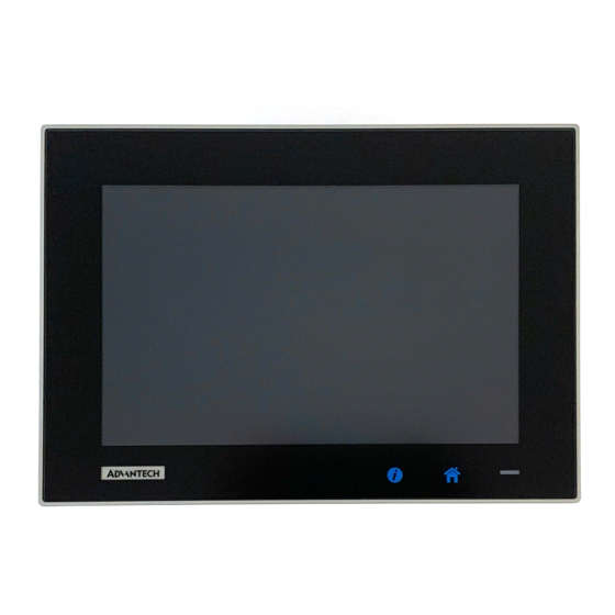
Advantech TPC-51WP Series User Manual
Industrial touch panel computers with intel atom processors
Hide thumbs
1
2
3
4
5
6
Table Of Contents
7
8
9
10
11
12
13
14
15
16
17
18
19
20
21
22
23
24
25
26
27
28
29
30
31
32
33
34
35
36
37
38
39
40
41
42
43
44
45
46
47
48
49
50
51
52
53
54
55
56
57
58
59
60
61
62
63
64
65
66
67
68
69
70
71
72
73
74
75
76
77
78
79
80
81
82
83
84
page
of
84
Go
/
84
Contents
Table of Contents
Bookmarks
Table of Contents
Table of Contents
Chapter 1 General Information
Introduction
Specifications
System Kernel
I/O Ports
O/S Support
Safety and Environment
LCD Specifications
Touchscreen Specifications
Power
I/O Ports Arrangement
Panel Mounting
Dimensions and Cutout
Chapter 2 System Setup
System Setup
Installing the Drivers
Transport and Unpacking
Panel Mounting
Cabinet Installation and Earth Grounding Setup
Power/Digital Ground and Earth Ground
Chapter 3 Features in Windows Embedded
Features in Windows Embedded
Enhanced Write Filter (EWF)
File-Based Write Filter (FBWF)
Horm
Appendix A Serial Port Settings
Jumper, Dip Switch and Connector Location
Top
Bottom
Jumper Setting and Description
CMOS Clear Function (CN1)
Switch Setting
Termination Resistor Select (SW3)
Connector Pin Definition
SATA Connector (CN12)
SATA Power Connector (CN13)
Mini PCIE Slot (MINIPCIE)
Cfast Slot (CN14)
Power in Connector (CN18)
LAN RJ45 Connector (CN7,CN8)
USB Connector (CN10)
COM1 RS232 Connector (CN15)
COM2 RS232/422/485 Connector (CN16)
Appendix B Driver Installation and Configuration
Intel Chipset Software Installation Utility Installation
Intel Graphics Driver Installation
LAN Driver Installation
Intel® Trusted Execution Engine Driver Installation
Windows 7 USB 3.0 Driver Installation
Advantech EC Driver Installation
Advantech EC Brightness Control Tool Installation
Advantech EC Watchdog Timer Driver Installation
Advantech Lmsensor Driver Installation
Appendix Cbios Setup
Entering Setup
Main Setup
Advanced BIOS Features Setup
Chipset Configuration
Security
Boot
Save & Exit
Advertisement
Quick Links
Download this manual
User Manual
TPC-1051WP/1551WP Series
Industrial Touch Panel Computers with
®
Intel
Atom™ Processors
Table of
Contents
Previous
Page
Next
Page
1
2
3
4
5
Advertisement
Table of Contents
Need help?
Do you have a question about the TPC-51WP Series and is the answer not in the manual?
Ask a question
Questions and answers
Related Manuals for Advantech TPC-51WP Series
Touch Panel Advantech TPC-1261H User Manual
Gx3 lx800 touch panel computer with 12.1" svga tft lcd (106 pages)
Touch Panel Advantech Intel XScale PXA Touch Panel Computer TPC-66 Series User Manual
Tpc-66 series intel xscale pxa touch panel computer with 5.7" cstn/ 5.6" (76 pages)
Touch Panel Advantech TPC-650H User Manual
5.7" vga tft lcd intel atom touch panel computer (42 pages)
Touch Panel Advantech TPC-1250H User Manual
12.1" svga tft lcd intel atom touch panel computer (42 pages)
Touch Panel Advantech TPC-1250H User Manual
Industrial touch panel computers with intel atom processors (30 pages)
Touch Panel Advantech TPC-1770 User Manual
Intel touch panel computer with high luminance 17" sxga tft lcd (56 pages)
Touch Panel Advantech TPC-1782H User Manual
Intel 4th generation core i computer (56 pages)
Touch Panel Advantech TPC-B510 User Manual
Industrial touch panel computer with 8th gen. intel core processor (89 pages)
Touch Panel Advantech TPC-1051WP Series User Manual
Industrial touch panel computers with intel atom processors (84 pages)
Touch Panel Advantech TPC-B610 User Manual
Industrial touch panel computer - modular computing box with intel 10th gen core i cpu socket (lga1200) (76 pages)
Touch Panel Advantech TPC-2000 Series User Manual
Industrial modular touch panel computer with intel atom/ celeron processor (74 pages)
Touch Panel Advantech TPC-100W Series User Manual
7"/10.1"/15.6" touch panel computer with arm® cortex®-a53 processor (48 pages)
Touch Panel Advantech TPC 40 Series User Manual
Multi-touch panel computer with amd dual-core processor (54 pages)
Touch Panel Advantech TPC-1840 User Manual
Multi-touch panel computer with amd dual-core processor (54 pages)
Touch Panel Advantech TPC-2140 User Manual
Multi-touch panel computer with amd dual-core processor (54 pages)
Touch Panel Advantech TPC-1582H-433BE User Manual
Intel 4th generation core i computer (56 pages)
This manual is also suitable for:
Tpc-1051wp series
Tpc-1551wp series
Tpc-1051wp-e3 series
Tpc-1551wp-e3 series
Table of Contents
Print
Rename the bookmark
Delete bookmark?
Delete from my manuals?
Login
Sign In
OR
Sign in with Facebook
Sign in with Google
Upload manual
Upload from disk
Upload from URL


Need help?
Do you have a question about the TPC-51WP Series and is the answer not in the manual?
Questions and answers