Intel Core 2 Duo User Manual
Intel processor and chipset
Hide thumbs
Also See for Core 2 Duo:
- User manual (81 pages) ,
- Installation instructions manual (11 pages) ,
- Datasheet (113 pages)

Related Manuals for Intel Core 2 Duo


Summary of Contents for Intel Core 2 Duo
- Page 1 ® Intel Core 2 Duo Processor and ® Intel Q35 Express Chipset Development Kit User’s Manual October 2007 Order Number: 318476-001US...
- Page 2 Contact your local Intel sales office or your distributor to obtain the latest specifications and before placing your product order. Copies of documents which have an order number and are referenced in this document, or other Intel literature may be obtained by calling 1-800-548-4725 or by visiting Intel's website at http://www.intel.com.
-
Page 3: Table Of Contents
Contents—Intel Core 2 Duo Processor and Intel Q35 Express Chipset Contents About This Manual ... 6 Content Overview... 6 Text Conventions ... 6 Glossary of Terms and Acronyms...7 Support Options ... 8 1.4.1 Electronic Support Systems ... 8 1.4.2 Additional Technical Support ...8 Product Literature ... - Page 4 1394a Header ...23 ® Intel Core 2 Duo Processor and Intel User’s Manual Intel Core 2 Duo Processor and Intel Q35 Express Chipset—Contents ® Q35 Express Chipset Development Kit Board ® Q35 Express Chipset Development Kit October 2007 Order Number: 318476-001US...
-
Page 5: Revision History
Revision History—Intel Core 2 Duo Processor and Intel Q35 Express Chipset Revision History Date Revision Description October 2007 Initial release ® ® Intel Core 2 Duo Processor and Intel Q35 Express Chipset Development Kit October 2007 User’s Manual Order Number: 318476-001US... -
Page 6: About This Manual
® Intel Core 2 Duo Processor and Intel User’s Manual Intel Core 2 Duo Processor and Intel Q35 Express Chipset—About This Manual ® Q35 Express Chipset Development Kit ® The pound symbol (#) appended to a signal name indicates that the signal is active low. -
Page 7: Glossary Of Terms And Acronyms
Definition (Sheet 1 of 2) Term Advanced Digital Display Card – 2 for an Intel Graphics Controller that supports ADD2+ cards. It plugs into a x16 PCI Express* connector but uses the multiplexed SDVO interface. The card adds Video In ADD2 Card capabilities to platform. -
Page 8: Support Options
Definition (Sheet 2 of 2) Term Advanced Digital Display Card – 2 for an Intel Graphics Controller that supports ADD2+ cards. It plugs into a x16 PCI Express* connector but uses the multiplexed SDVO interface. The card adds Video In ADD2 Card capabilities to platform. -
Page 9: Intel Literature Centers
About This Manual—Intel Core 2 Duo Processor and Intel Q35 Express Chipset Table 2. Intel Literature Centers Location U.S. and Canada U.S. (from overseas) Europe (U.K.) Germany France Japan (fax only) October 2007 Order Number: 318476001US Telephone Number 1-800-548-4725 708-296-9333... -
Page 10: Development Kit Hardware Features
Intel Core 2 Duo Processor and Intel Q35 Express Chipset—Development Kit Hardware Features Development Kit Hardware Features This chapter describes the features of the Intel® Q35 Development Kit. These recommendations would largely apply to other designs incorporating Intel® Q35 chipset. This documentation should be used in conjunction with the datasheets, specification updates and platform design guides for the Intel®... -
Page 11: System Block Diagram
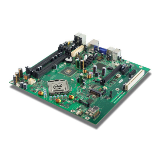
Development Kit Hardware Features—Intel Core 2 Duo Processor and Intel Q35 Express Chipset Figure 1. Board Features PCI Slot PCI Express x1 Slot SPI EEPROM (Secondary) SPI EEPROM (Primary) PCI Express x16 Graphics Slot Intel® I/O Controller Hub (ICH) SATA Port... -
Page 12: Development Kit Inventory Checklists
Intel Core 2 Duo Processor and Intel Q35 Express Chipset—Development Kit Hardware Features Figure 2. Intel® Q35 Express Chipset Development Kit block diagram Development Kit Inventory Checklists This section describes major hardware items which should be available on this development kit. -
Page 13: Development Kit Board Specification
Development Kit Hardware Features—Intel Core 2 Duo Processor and Intel Q35 Express Chipset Table 4. Development Kit Board Specification 1 PCI Express x16, 2 PCIe x1, 1 PCI expansion slots 1394a • 1 front panel headers for support of 1 port •... -
Page 14: Processor Support
• Intel Pentium ® • Intel Celeron Refer to this link for other processors which is also supported by Intel® Q35 Express Chipset. http://developer.intel.com/products/chipsets/Q35_Q33/index.htm System Memory The Intel® Q35 Express Chipset supports two types of memory organization. These are interleaved mode and asymmetric mode. The Q35 supports: Listed here are the summary of the system memory supported. -
Page 15: Dual Channel (Interleaved) Mode Configurations
Development Kit Hardware Features—Intel Core 2 Duo Processor and Intel Q35 Express Chipset • Non-ECC DDR2 (667/800) • 512Mb, 1Gb and 2Gb technology • 4 DIMMs, 4GB maximum per channel, 8GB total memory • Dual channel (Interleaved) mode. This mode offers the highest throughput for real world applications. -
Page 16: Dual Channel (Interleaved) Mode Configuration With 2X Dimms
Intel Core 2 Duo Processor and Intel Q35 Express Chipset—Development Kit Hardware Features Figure 4. Dual Channel (Interleaved) Mode Configuration with 2x DIMMs Figure 5 shows a dual channel configuration using 3 DIMMs. In this example, the combined capacity of the two DIMMs in Channel A equal the capacity of the single DIMM in the DIMM 0 socket of Channel B. -
Page 17: Single Channel (Asymmetric) Mode Configurations
Development Kit Hardware Features—Intel Core 2 Duo Processor and Intel Q35 Express Chipset Figure 6. Dual Channel (Interleaved) Mode Configuration with 4x DIMMs 2.5.2 Single Channel (Asymmetric) Mode Configurations Figure 7 shows a single channel configuration using 1x DIMM. In this example, only the DIMM 0 socket of Channel A is populated. -
Page 18: Back-Panel Connectors
Intel Core 2 Duo Processor and Intel Q35 Express Chipset—Development Kit Hardware Features Figure 8. Single Channel (Asymmetric) Mode Configuration with 3x DIMMs Back-Panel Connectors Figure 9 shows back-panel connectors for the development kit. Figure 9. Back-panel Connectors 1394a Port... -
Page 19: Lan Connector With Integrated Leds
Development Kit Hardware Features—Intel Core 2 Duo Processor and Intel Q35 Express Chipset Center/Subwoofer Speaker Out Jack (Orange) This audio jack is used to connect to center/subwoofer speakers in a 5.1 and 7.1- channel audio configuration. Rear Speaker Out (Black) This audio jack is used to connect to rear speakers in a 5.1 and 7.1-channel audio... -
Page 20: Debug Features
Intel Core 2 Duo Processor and Intel Q35 Express Chipset—Development Kit Hardware Features Debug Features 2.7.1 Extended Debug Probe (XDP) The reference board provides a JTAG-compliant test access port (TAP) for attachment of an XDP connector. The XDP connector and associated circuitry enable the use of the ITP for the particular processor to interrupt the boot sequence and view processor status. -
Page 21: Voltage Reference
Development Kit Hardware Features—Intel Core 2 Duo Processor and Intel Q35 Express Chipset 2.7.4 Voltage Reference Table 9 for details of the expected voltage levels for each voltage rail on the CRB. Table 9. Voltage Reference detail Voltage Rail VCC3... -
Page 22: Jumper Functions
Intel Core 2 Duo Processor and Intel Q35 Express Chipset—Development Kit Hardware Features 2.8.1 Jumper Functions Table 10 provides a list of the setting definitions for the Intel ® and Intel Q35 Express Chipset Development Kit. ® Table 10. Intel... -
Page 23: Spi Removal / Installation Technique
Development Kit Hardware Features—Intel Core 2 Duo Processor and Intel Q35 Express Chipset Figure 13. Location for 1394a Header and USB Front Panel U1FW (USB Front Panel) Table 12. 1394a Header Pin Number SPI Removal / Installation Technique When removing or installing the SPI device, care must be taken to avoid damage to the SPI socket. -
Page 24: Spi Device Removal
Intel Core 2 Duo Processor and Intel Q35 Express Chipset—Development Kit Hardware Features 2.9.1 SPI Device Removal To remove the SPI device from the socket, use a tweezer tip to gently pry one leg of the cap away from the socket. There is a small latch on the bottom of the leg of the cap. -
Page 25: Spi Device Installation
Development Kit Hardware Features—Intel Core 2 Duo Processor and Intel Q35 Express Chipset Figure 15. SPI Device Installation 1. Place the fresh IC into the socket. Match pin 1. on the IC to pin 1 on the socket. 3. Lock the cover with the hook. -
Page 26: Setting Up And Configuring The Development Kit
Intel Core 2 Duo Processor and Intel Q35 Express Chipset—Setting Up and Configuring the Setting Up and Configuring the Development Kit This chapter discusses basic board set up and operation. Please refer to the board layout, jumper setting location and the component reference designator. -
Page 27: Mounting Hole Locations
Setting Up and Configuring the Development Kit—Intel Core 2 Duo Processor and Intel Q35 Express Chipset environment. Since the board is not in a protective chassis, the user is required to observe extra precautions when handling and operating the system. -
Page 28: Btx Heatsink Setup With Srm
Intel Core 2 Duo Processor and Intel Q35 Express Chipset—Setting Up and Configuring the Figure 18. Mounting the Standoff for BTX Heatsink BTX Heatsink Setup with SRM This section describes BTX casing which uses “Support and Retention Module (SRM)” as... -
Page 29: Intel ® Core Tm
Setting Up and Configuring the Development Kit—Intel Core 2 Duo Processor and Intel Q35 Express Chipset 1. Place the uBTX board on the Support and Retention Module (SRM) so that the holes A, B, C and D on the PCB line up with the corresponding locations on the SRM (see Figure 19). -
Page 30: Board Setup And Configuration Before Boot
Intel Core 2 Duo Processor and Intel Q35 Express Chipset—Setting Up and Configuring the Figure 22. Tightening Heatsink on the SRM and Board Board Setup and Configuration before Boot Follow the steps below to operate the board. Warning: Before starting, ensure the power supply is not connected to the board. -
Page 31: Cpu Fan Location
Setting Up and Configuring the Development Kit—Intel Core 2 Duo Processor and Intel Q35 Express Chipset 2. Set jumpers to default positions. Refer to 3. Install the processor and ensure the 4-pin CPU fan power connector is installed on header shown in Figure 23. -
Page 32: Post Codes Definitions
Intel Core 2 Duo Processor and Intel Q35 Express Chipset—Setting Up and Configuring the Figure 24. 2x12 Standard power supply and 2x2 power supply Post Codes Definitions The CRB BIOS writes progress and error codes to Port 80 during POST. These codes are defined below. - Page 33 Setting Up and Configuring the Development Kit—Intel Core 2 Duo Processor and Intel Q35 Express Chipset E1-E8 EC-EE Boot Block Recovery Code Checkpoints Runtime POST Code Checkpoints October 2007 Order Number: 318476001US Restore CPUID value to register. Bootblock runtime module transferred to system memory.
- Page 34 Intel Core 2 Duo Processor and Intel Q35 Express Chipset—Setting Up and Configuring the ® Intel Core 2 Duo Processor and Intel User’s Manual Initialize CPU. The BAT test performed on KBC. Auto detection of KB and MS. Early CPU Init Start. Disable cache and init local APIC.
- Page 35 Setting Up and Configuring the Development Kit—Intel Core 2 Duo Processor and Intel Q35 Express Chipset 61-70 October 2007 Order Number: 318476001US Initialize NUM-LOCK status and program typematic rate. Initialize INT-13 and prepare for IPL detection. Initialize IPL devices controlled by BIOS and option ROMs.
-
Page 36: User's Manual October
Intel Core 2 Duo Processor and Intel Q35 Express Chipset—Setting Up and Configuring the Development Kit ® ® Intel Core 2 Duo Processor and Intel Q35 Express Chipset Development Kit User’s Manual October 2007 Order Number: 318476001US...
Need help?
Do you have a question about the Core 2 Duo and is the answer not in the manual?
Questions and answers