
Related Manuals for VarTech Systems VTPC190P


Summary of Contents for VarTech Systems VTPC190P
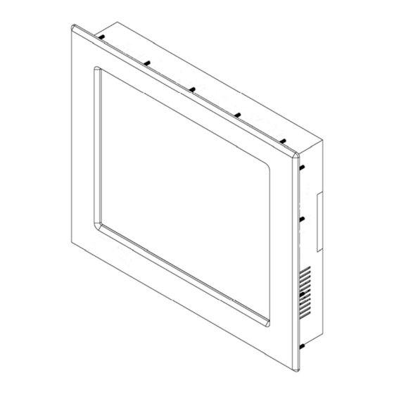
- Page 1 Solutions for Demanding Applications VARTECH S Y S T E M S I N C. 19.0” Panel Mount PC Model VTPC190P / PSS User’s Guide Read these instructions completely before attempting to operate your new Panel Mount PC...
- Page 2 Revision History Date Rev No Summary Page 8/11/08 First Issue 10/13/08 Revised panel mounting drawing 7/10/09 Revised Detail A, connector view & system spec. 4, 6 & 7 5/27/10 Corrected DC power rating misprint 8/15/12 Updated LCD Display Specs 8/15/12 Updated Computer Specs 8/15/12 Updated Power Specs...
- Page 3 Safety Instructions Read the Safety Instructions carefully and keep it for use later. The chassis metalwork of the module must be installed properly to the main earthing termination for Class 1 equipment. Care must be exercised in the application of the system to prevent overheating. Ensure that the ambient temperature around the system does not exceed 60°C and provide adequate means of ventilation to achieve this.
-
Page 4: Computer System
Standard Technical Specifications: Standard Monitor: Size / Type 19.0” SXGA TFT LCD Native Resolution 1280 x 1024 Contrast Ratio 800:1 Horizontal: 89° Viewing Angles Vertical: 89° Pixel Pitch 0.294mm Brightness (typical) 300 cd/m² Response Time (typical) Colors Supported 16.7 million Computer System: Processor Intel Pentium Dual Core Processor T4500 2.30 GHz 800MHz FSB... - Page 5 5 to 65°C, 28% RH NC Installation of Your Panel PC Packaged with each carton will be: 1 - VTPC190P / PSS 1 - AC Power Cable (Not included with DC option) 1 - #10-32 Mounting Hardware 1 - Users Guide (Printed or on CD)
- Page 6 ATTENTION: Mounting nuts must be tightened to a torque of 24 inch-pounds to provide a proper panel seal and avoid potential damage. Vartech Systems assumes no responsibility for water or chemical damage to the monitor or other equipment within the enclosure due to improper installation.
- Page 7 Panel Mount Drawing: Detail –A– Connections to the Panel Mount PC Bottom Rear View - Connector Panel - Power Connection (Power In) 19.0 Panel Mount PC 486-0010-01-02...
- Page 8 AC Models: The Panel Mount PC includes an AC line cord which is 6ft long. The power input receptacle is located on the bottom rear panel of the system. DC Models: The Panel Mount PC with two binding posts, one red and one black. Red is for connecting +9-32VDC and black is for power ground.
- Page 9 All LCD/LED monitors need time to become thermally stable the first time you turn them on. Therefore, to achieve more accurate adjustments for parameters, allow the LCD/LED monitor to warm (be on) for at least 20 minutes before making any screen adjustments. Maintenance The Panel Mount PC is designed to provide optimum service and performance with minimal maintenance including the occasional external cleaning.
-
Page 10: Award Bios Utility
Award BIOS Utility The Phoenix-Award BIOS provides users with a built-in Setup program to modify basic system configuration. All configured parameters are stored in a battery-backed-up RAM (CMOS RAM) to save the Setup information whenever the power is turned off. Entering Setup There are two ways to enter the Setup program. -
Page 11: Getting Help
Getting Help Main Menu The online description of the highlighted setup function is displayed at the bottom of the screen. Status Page Setup Menu/Option Page Setup Menu Press <F1> to pop out a small Help window that provides the description of using appropriate keys and possible selections for highlighted items. -
Page 12: Standard Cmos Setup Menu
Standard CMOS Setup Menu The Standard CMOS Setup Menu displays basic information about your system. Use arrow keys to highlight each item, and use <PgUp> or <PgDn> key to select the value you want in each item. Date The date format is <day>, <date> <month> <year>. Press <F3> to show the calendar. It is determined by the BIOS and read only, from Sunday to Saturday. - Page 13 IDE Channel 0~3 Master/IDE Channel 0~2 Slave These items identify the types of each IDE channel installed in the computer. There are 45 predefined types (Type 1 to Type 45) and 2 user’s definable types (Type User) for Enhanced IDE BIOS.
- Page 14 Halt On This item determines whether the system will halt or not, if an error is detected while powering up. No errors The system booting will halt on any errors detected. (default) All errors Whenever BIOS detects a non-fatal error, the system will stop and you will be prompted.
-
Page 15: Advanced Bios Features
Advanced BIOS Features This section allows you to configure and improve your system, to set up some system features according to your preference. 19.0 Panel Mount PC 486-0010-01-02... - Page 16 CPU Feature Scroll to this item and press <Enter> to view the CPU Feature sub menu. Hard Disk Boot Priority Scroll to this item and press <Enter> to view the sub menu to decide the disk boot priority Press <Esc> to return to the Advanced BIOS Features page. 19.0 Panel Mount PC 486-0010-01-02...
- Page 17 Virus Warning This function allows you to choose the VIRUS Warning feature for IDF Hard Disk boot sector protection. If this function is enabled and attempt to write data into this area, BIOS will show a warning message on screen and alarm beep. CPU L1 &...
- Page 18 Boot Up NumLock Status Set the the Num Lock status when the system is powered on. The default value is “On”. Gate A20 Option The default value is “Fast”. Normal The A20 signal is controlled by keyboard controller or chipset hardware. Fast Default: Fast.
- Page 19 APIC Mode Use this item to enable or disable APIC (Advanced Programmable Interrupt Controller) mode that provides symmetric multi-processing (SMP) for systems. MPS Version Control For OS This item specifies the version of the Multiprocessor Specification (MPS). Version 1.4 has extended configuration tables to improve support for multiple PCI bus configurations and provide future expandability.
-
Page 20: Advanced Chipset Features
Advanced Chipset Features This section contains completely optimized chipset’s features on the board that you are strongly recommended to leave all items on this page at their default values unless you are very familiar with the technical specifications of your system hardware. System BIOS Cacheable Selecting Enabled allows caching of the system BIOS ROM at F0000h-FFFFFh, resulting in better system performance. - Page 21 PCI Express Root Port Func Scroll to this item and press <Enter> to view the sub menu to decide the PCI Express Port. Press <Esc> to return to the Advanced Chipset Featurs page, and press it again, return to the Main Menu page.
- Page 22 DVMT/Fixed Memory Size DVMT (Dynamic Video Memory Technology) allows you to select a maximum size of dynamic amount usage of the video memory. The system would configure the video memory dependent on your application. Boot Display This item is to select Display Device that the screen will be shown. Panel Scaling This item shows the setting of panel scaling and operates the scaling function that the panel output can fit the screen resolution connected to the output port.
- Page 23 Integrated Peripherals This section allows you to configure your SuperIO Device, IDE Function and Onboard Device. 19.0 Panel Mount PC 486-0010-01-02...
- Page 24 OnChip IDE Device Scroll to this item and press <Enter> to view the sub menu OnChip IDE Device. IDE HDD Block Mode Block mode is also called block transfer, multiple commands, or multiple sector read/write. If your IDE hard drive supports block mode (most new drives do), select Enabled for automatic detection of the optimal number of block read/writes per sector the drive can support.
- Page 25 *** On-Chip PATA Setting *** On-Chip Primary/Secondary PCI IDE The integrated peripheral controller contains an IDE interface with support for two IDE channels. Select Enabled to activate each channel separately. The default value is “Enabled”. NOTE: Choosing Disabled for these options will automatically remove the IDE Primary Master/ Slave PIO and/or IDE Secondary Master/Slave PIO items on the menu.
- Page 26 Super IO Device Scroll to this item and press <Enter> to view the sub menu Super IO Device Onboard FDC Controller Select Enabled, if your system has a floppy disk controller (FDC) installed on the system board and you want to use it. If you install and-in FDC or the system has no floppy drive, select Disabled in this field.
-
Page 27: Usb 1.0 Controller
USB Device Setting Scroll to this item and press <Enter> to view the sub menu USB Device Setting USB 1.0 Controller Enable this item if you are using the USB 1.0 in the system. You should disable this item if a higher-level controller is added. -
Page 28: Power Management Setup
Power Management Setup The Power Management Setup allows you to save energy of your system effectively. It will shut down the hard disk and turn OFF video display after a period of inactivity. ACPI Function This item allows you to enable/disable the Advanced Configuration and Power Management (ACPI). - Page 29 Power Management This option allows you to select the type (or degree) of power saving for Doze, Standby, and Suspend modes. The table below describes each power management mode: It is maximum power savings, only available for SL Max Saving CPUs.
- Page 30 Suspend Mode After a selected period of system inactivity (1 minute to 1 hour), all devices except the CPU shut off. The default value is “Disabled”. Disabled The System will never enter the SUSPEND mode. It defines continuous idle time before the system 1/2/4/6/8/10/2 entering the SUSPEND mode.
-
Page 31: Pnp/Pci Configuration Setup
PnP/PCI Configuration Setup This section describes the configuration of PCI (Personal Computer Interconnect) bus system, which allows I/O devices to operate at speeds close to the CPU speed while communicating with other important components. This section covers very technical items that only experienced users could change default settings. - Page 32 ** PCI Express relative items ** Maximum Payload Size When using DDR SDRAM and Buffer size selection, another consideration in designing a payload memory is the size of the buffer for data storage. Maximum Payload Size defines the maximum TLP (Transaction Layer Packet) data payload size for the device. Press <Esc>...
-
Page 33: Pc Health Status
PC Health Status This section supports hardware monitering that lets you monitor those parameters for critical voltages, temperatures and fan speed of the board. Shutdown Temperature It helps you set the maximum temperature they system can reach before powering down. Current SYSTEM Temperature Show you the current system1 temperature. -
Page 34: Frequency/Voltage Control
Frequency/Voltage Control This section is to control the CPU frequency and Supply Voltage, DIMM OverVoltage and AGP voltage. Auto Detect PCI Clk The item enables or disables the auto detection of the PCI clock. Spread Spectrum This item is to adjust extreme values of the pulse for EMI test. Press <Esc>... -
Page 35: Load Optimized Defaults
Load Optimized Defaults This option allows you to load your system configuration with default values. These default settings are optimized to enable high performance features. To load CMOS SRAM with SETUP default values, please enter “Y”. If not, please enter “N”. 19.0 Panel Mount PC 486-0010-01-02... -
Page 36: Set Supervisor/User Password
Set Supervisor/User Password You can set a supervisor or user password, or both of them. The differences between them are: Supervisor password: You can enter and change the options on the setup menu. User password: You can just enter, but have no right to change the options on the setup menu. When you select this function, the following message will appear at the center of the screen to assist you in creating a password. -
Page 37: Save And Exit Setup
Save & Exit Setup This section allows you to determine whether or not to accept your modifications. Type “Y” to quit the setup utility and save all changes into the CMOS memory. Type “N” to bring you back to the Setup utility. -
Page 38: Exit Without Saving
Exit Without Saving Select this option to exit the Setup utility without saving changes you have made in this session. Type “Y”, and it will quit the Setup utility without saving your modifications. Type “N” to return to the Setup utility. -
Page 39: Watchdog Timer
A p p e n d i x A Watchdog Timer Watchdog Timer Setting After the system stops working for a while, it can be auto-reset by the Watchdog Timer. The integrated Watchdog Timer can be set up in the system reset mode by program. Using the Watchdog Function Start ... - Page 40 ; IF to disable WDT: O 2E 30 O 2F 00 ; Can be disable at any time Timeout Value Range 1 to 255 Minute / Second Program Sample 2E, 87 2E, 87 2E, 07 2F, 08 Logical Device 8 2E, 30 Activate 2F, 01...
- Page 41 A p p e n d i x B Digital I/O Using the Digital Input Function Start Un-Lock SuperI /O: O 2E 87 ; Un-lock super I/O O 2E 87 ; Un-lock super I/O SelectMultiplexed pin to GPIO Function: O 2E 2A O 2F FF ...
- Page 42 Output Data: O 2E F1 O 2F XX=00,01,02,…FF (XX is Output Data) For Additional Assistance Contact Your VarTech Sales Representative Vartech Systems, Inc. 11529 Sun Belt Ct. Baton Rouge, LA 70809 800-223-8050 Fax: 225-297-2440 www.vartechsystems.com 19.0 Panel Mount PC...
Need help?
Do you have a question about the VTPC190P and is the answer not in the manual?
Questions and answers