Hitachi VB 13Y Technical Data And Service Manual
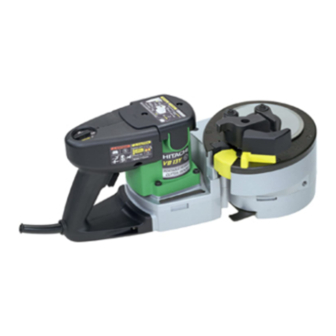
Portable rebar cutter/bender
Hide thumbs
Also See for VB 13Y:
- Handling instructions manual (43 pages) ,
- Handling instructions manual (34 pages)

Related Manuals for Hitachi VB 13Y


Summary of Contents for Hitachi VB 13Y
- Page 1 MODEL VB 13Y POWER TOOLS TECHNICAL DATA PORTABLE REBAR CUTTER/BENDER VB 13Y SERVICE MANUAL LIST No. 0782 Jan. 2000 SPECIFICATIONS AND PARTS ARE SUBJECT TO CHANGE FOR IMPROVEMENT...
- Page 2 REMARK: Throughout this TECHNICAL DATA AND SERVICE MANUAL, a symbol(s) is(are) used in the place of company name(s) and model name(s) of our competitor(s). The symbol(s) utilized here is(are) as follows: Competitors Symbols Utilized Model Name Company Name CB-13 DR-12E ALBA...
-
Page 3: Table Of Contents
Notice for use Specifications and parts are subject to change for improvement. Refer to Hitachi Power Tool Technical News for further information. CONTENTS [ Business Section ] Page 1. PRODUCT NAME • • • • • • • • • • • • • • • • • • • • • • • • • • • • • • • • • • • • • • • • • • • • • • • • • • • • • • • • • • • • • • • • • • • • • • • • • • • • • • • • • • • • • • • • • • • • • • • • • • • • • • • • • • • • • • • • • • • • • • • •... -
Page 4: Product Name
1. PRODUCT NAME Hitachi Portable Rebar Cutter/Bender, Model VB 13Y 2. MARKETING OBJECTIVE A compact and lightweight power tool that reduces worker fatigue and enhances work efficiency. 3. APPLICATIONS Cutting and bending of rebars (concrete reinforcing rod) during construction of foundations and external structures. -
Page 5: Selling Point Descriptions
(5/8")), the Model VB 13Y is half the price of the electro-hydraulic cutter/bender and the cost/performance ratio is excellent. This is because the Model VB 13Y is equipped with a gear and a cam instead of a hydraulic system for cutting rebars, and an advanced microprocessor instead of an electromagnetic clutch for bending rebars. - Page 6 5-1-10. Low height The Model VB 13Y has a unique design, with the bending unit being lower than the motor unit, to give the bender added stability when bending long rebars. Although the maximum capacity rebar diameter is smaller than another maker's electric cutter/bender, the Model VB 13Y is convenient to use thanks to its lower height (135 mm (5-5/ 16")) while the other maker's electric cutter/bender is 245 mm (9-41/64") high.
-
Page 7: Specifications
6. SPECIFICATIONS VB 13Y Model (1) Material; Rebar: Yield strength 460N/mm (47 kgf/mm ) max. Capacities GRADE 460 (Great Britain) BST 500 (Germany) B 500 (Spain) GRADE 40 (U.S.A.) or equivalent grades (2) Diameter of material: 8 --- 13 mm (3/8" --- 1/2")) -
Page 8: Comparisons With Similar Products
Weight 12.0 11.5 12.3 (excluding cord) (26.5 Ibs.) (25.4 Ibs.) (27.1 Ibs.) 7-1. Working Efficiency Comparison Maker HITACHI Model name VB 13Y Capacity Rebar Dia. (1/2") (1/2") (1/2") Motorized gear Manual Manual Drive System drive system Cutting Time seconds/operation Bending Time (180˚) seconds/operation * The data shown in the above table are mean values of 50 bending operations. -
Page 9: How To Use This Unit
8. HOW TO USE THIS UNIT (1) Cutting work (Fig. 7) Rebar Cutter Variable-speed switch Fig. 7 Alignment marks Setting dial (2) Bending work (Fig. 8) Rebar To switch between cutting and bending To adjust bending angle (0 fl --- 180 fl) Fig. -
Page 10: Service Life Of Cutter
10. PRECAUTIONS IN SALES PROMOTION In the interest of promoting the safest and most efficient use of the Model VB 13Y Portable Rebar Cutter/Bender by all of our customers, it is very important that at the time of sale the salesperson carefully ensures that the buyer seriously recognizes the importance of the contents of the Handling Instructions, and fully understands the meaning of the precautions listed on the Caution Plate attached to each tool. -
Page 11: Safety Instructions
(2) While turning the switch on, never put your hand close to the cutter. For the sake of safe operation, the Model VB 13Y is designed as follows: Cutter cover is provided. -
Page 12: Pictograph Illustration And Explanation
11-1. Pictograph Illustration and Explanation If the switch is turned off and then immediately turned on again, the Do not use or leave this electric motor may not start. Wait for at power tool in wet weather least one full second before conditions. -
Page 13: Precautions In Disassembly And Reassembly
12. PRECAUTIONS IN DISASSEMBLY AND REASSEMBLY The [Bold] numbers in the descriptions below correspond to the item numbers in the Parts List and exploded assembly diagram. 12-1. Disassembly (1) Disassembly of the handle (Fig. 10) Remove the two Tapping Screws (W/Flange) D4 x 20 [81] and the Tail Cover [82]. Remove the two Tapping Screws (W/Flange) D5 x 20 [104], four Tapping Screws D4 x 20 (W/Flange) [81] and two Machine Screws (W/Washers) M5 x 20 [105] to remove the Handle (A).(B) Set [94]. - Page 14 (3) Disassembly of the power supply unit 1) Removal of the Controller Circuit [95] (Fig. 10) Remove the rubber bushing and pull out the cable of the Controller Circuit [95] from the Gear Cover Ass'y [22]. Disconnect the cable connector from the cable and separate the Controller Circuit [95] from the Gear Cover Ass'y [22].
- Page 15 (5) Disassembly of the gear (Figs. 13, 14 and 15) 1) Remove the two Hex. Socket Hd. Bolts (W/Flange) M4 x 10 [58] from the bottom of the Gear Cover Ass'y [22] and remove the Sensor Cover [28] and the O-Ring (S-85) [27]. 2) Mark the engagement point between the Sensor Gear [26] and the Sensor Gear [56] with a magic marker as shown in Fig.
- Page 16 [18] [19] Third Pinion First Pinion (B) [12] Second Pinion Fig. 15 (6) Disassembly of the gear unit (Figs. 16, 17 and 18) 1) Press First Pinion (B) [55] in A direction with a hand press supporting the surfaces B and C respectively. Then remove Sleeve (B) [50], First Gear (B) [51], Clutch Spring [52], Collar (A) [53] and Washer [54] (Fig.
- Page 17 [13] [38] [63] Hook [64] [13] [36] [68] [73] [37] [34] [39] [66] [65] [67] [67] Fig. 19 Fig. 20 (8) Disassembly of bracket (A) and (B) unit (Fig. 20) Press the Bolt (A) [65] with a hand press supporting Bracket (A) [68]. Then the Feather Key [66], Bracket (A) [68] and Bracket (B) [73] can be removed.
-
Page 18: Reassembly
12-2. Reassembly Reassembly can generally be carried out as the reverse of the disassembly procedure, with some items to be noted as follows. (1) Reassembly of the cam shaft unit (Fig. 22) [34] Perform reassembly so that the chamfered portion of the Cam Shaft [12] is aligned with the pins of the Cam [8] in the same direction. -
Page 19: Wiring Diagram
(5) Reassembly of bending unit (Figs. 12 and 22) Mount the Cam Cover [6], Turn Table [5] and Center Plate (A) [3] in the reverse of the disassembly procedure. Before mounting the Center Plate (A) [3], apply grease (TUFREX 251) to the 18 mm dia. hole of Center Plate (A) [3] adequately. -
Page 20: Confirmation After Reassembly
For products with noise suppressor CR Unit (0.022 µF + 5 KΩ) Switch Stator Choke Coil 8 µH Cord Printed Circuit Armature Board Ass'y Choke Coil 5 µH CR Unit Stator (0.022 µF + 5 KΩ) Capacitor Control Circuit Ass'y (0.22 µF + 2 x 3300 pF) Fig. - Page 21 <Starting position for backward rotation> Marked line for 13 mm dia. bar Marking on the angle gauge [100] Check the starting position for backward rotation. Fig. 29 Fig. 28 (2) Adjust the bending accuracy as follows (Fig. 30). 1) Unplug the power cord from the receptacle. 2) Slightly turn the fine-adjustment control on the Controller Circuit [95] with a screwdriver.
-
Page 22: Repair Procedure
12-5. Repair Procedure Following table shows rough repair procedures. Refer to the above mentioned disassembly and reassembly procedures for details. * Be sure to confirm the operation of the controller circuit, gears, brackets and cam after reassembly of them, and perform adjustment if necessary. -
Page 23: Tightening Torque
12-6. Tightening Torque Machine Screw (W/Washers) 0.7 N m (35 7 kgf cm) (30.4 6.1 in-Ibs.) • • Seal Lock Screw 0.4 N m (18 4 kgf cm) (15.6 3.5 in-Ibs.) • • 0.4 N m (18 4 kgf cm) (15.6 3.5 in-Ibs.) Machine Screw •... -
Page 24: Standard Repair Time (Unit) Schedules
13. STANDARD REPAIR TIME (UNIT) SCHEDULES Variable 70 min. MODEL Fixed Work Flow VB 13Y Tail Cover Handle (A).(B) Housing Ass'y Bearing Controller Bushing (B) Circuit Ball Bearing O-Ring (608VV) x 2 Volume Holder Stator Ass'y Ass'y Fan Guide Steel Bar... -
Page 25: Assembly Diagram For Vb 13Y
Assembly Diagram for VB 13Y --- 22 ---... - Page 26 VB 13Y PARTS ITEM CODE NO. DESCRIPTION REMARKS USED 998-471 HEX. SOCKET HD. BOLT M5X12 316-224 WASHER 318-288 CENTER PLATE (A) 873-570 O-RING (P-18) 316-220 TURN TABLE 316-219 CAM COVER 316-216 FELT PACKING 316-199 939-540 RETAINING RING FOR D10 SHAFT (10 PCS.)
- Page 27 VB 13Y PARTS ITEM CODE NO. DESCRIPTION REMARKS USED 316-209 CLUTCH SPRING 316-208 COLLAR (A) 981-077 WASHER 318-359 FIRST PINION (B) 316-212 SENSOR GEAR 962-569 WASHER (B) 316-228 HEX. SOCKET HD. BOLT (W/FLANGE) M4X10 316-226 STEEL BAR GUIDE 316-190 NEEDLE...
-
Page 28: Standard Accessories
VB 13Y PARTS ITEM CODE NO. DESCRIPTION REMARKS USED 995-362 SWITCH RUBBER COVER 318-280 SWITCH (2P PLUG IN TYPE) W/O LOCK 302-089 TAPPING SCREW (W/FLANGE) D5X20 (BLACK) 316-229 MACHINE SCREW (W/WASHERS) M5X20 (BLACK) 981-373 TUBE (D) FOR CORD 984-750 TAPPING SCREW (W/FLANGE) D4X16...
Need help?
Do you have a question about the VB 13Y and is the answer not in the manual?
Questions and answers