
Related Manuals for HAMPTON BAY Bentley II 328 478


Summary of Contents for HAMPTON BAY Bentley II 328 478
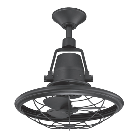
- Page 1 328 478 Bentley II Ceiling Fan Owner’s Manual Bentley II Ventilador de Techo de 33 Manual del Propietario...
- Page 2 Bentley II by Hampton Bay ®...
-
Page 3: Table Of Contents
13” Bentley II Thank you for purchasing our ceiling fan. This product has been manufactured with the highest standards of safety and quality. Ceiling Fan by Hampton Bay Date Purchased Table of Contents Store Purchased Safety Rules ....1 328-478 Model No. -
Page 4: Safety Rules
Safety Rules - Read and Save These Instructions To reduce the risk of electric shock, insure electricity has been turned off After making electrical connections, spliced conductors should be turned at the circuit breaker or fuse box before beginning. upward and pushed carefully up into outlet box. The wires should be spread apart with the grounded conductor and the equipment-grounding All wiring must be in accordance with the National Electrical Code conductor on one side of the outlet box and ungrounded conductor on the... -
Page 5: Unpacking Your Fan
Unpacking Your Fan Unpack your fan and check the contents. You should have the following items: Canopy assembly 3-speed wall control with 2 mounting Electrical Hardware screws and 4 wire nuts (3 Plastic Wire Nuts) Ball/downrod assembly Mounting plate with 2 mounting screws Coupling cover Allen wrench Fan motor assembly... -
Page 6: Installing Your Fan
Installing Your Fan Tools Required Figures 1~2 are examples of different ways to mount the outlet box. Phillips screwdriver, straight slot screwdriver, step ladder and wire cutters. Outlet Box Figure 3 To hang your fan where there is an existing fixture Mounting Options but no ceiling joist, you may need an installation Outlet Box... -
Page 7: Hanging The Fan
Hanging the Fan Align the holes at the bottom of the downrod Pin in Locked with the holes in the coupling on top of the Positioon Motor Wires REMEMBER to turn off the power. Follow the motor housing (Figure 5). Carefully insert the Ball/Downrod clevis pin through the holes in the collar and steps below to hang your fan properly. -
Page 8: Installing Fan To The Electrical Box
Installing Fan to ETL Listed Outlet Box the Electrical Box WARNING 120V Wires TO REDUCE THE RISK OF FIRE, ELECTRIC SHOCK OTHER PERSONAL INJURY. MOUNT FAN ONLY TO AN OUTLET BOX OR SUPPORTING SYSTEM MARKED ACCEPTABLE Ceiling Mounting FOR FAN SUPPORT AND USE THE MOUNTING SCREWS PROVIDED WITH THE OUTLET BOX. -
Page 9: Making The Electrical Connections
Making the Electrical Connections Wall Outlet Box Switch Wall Plate WARNING TO AVOID POSSIBLE ELECTRICAL SHOCK, BE SURE ELECTRICITY IS TURNED OFF AT THE Screws Screws MAIN FUSE BOX BEFORE WIRING. NOTE INSTALLATION OF THIS FAN REQUIRES THAT A THREE-CONDUCTOR CABLE WITH GROUND WIRE BE RUN BETWEEN CEILING AND WALL OUTLET BOX, OR THE OSCILLAT- ING FEATURE WILL NOT WORK. - Page 10 SUPPLY CIRCUIT Ground Conductor Ceiling Outlet Box BLACK WHITE Green Ground Lead BLUE (or RED) BLUE BLUE (or RED) WHITE BLACK Ground to BLACKW/WHITE BLACK Downrod YELLOW/GREEN GROUND Wall Outlet Box Speed/oscillation Switch • Dash lines are 3-conductor cable between ceiling and wall outlet box. Figure 10...
- Page 11 Installing the Wall Finishing the Fan WARNING MAKE SURE THE TAB ON THE HANGING Installation Transmtter BRACKET PROPERLY SITS IN THE GROOVE IN THE HANGER BALL BEFORE ATTACH- Remember to shut the power off at the circuit ING THE CANOPY TO THE BRACKET BY Tuck connections neatly into ceiling outlet TURNING THE HOUSING UNTIL IT DROPS breaker or fuse box.
- Page 12 Disassembling Your Fan This fan is pre-assembled the rear guard, blade and front guard in factory before shipping for your easy installation, checking all screws are tighten and securely in place, following the below procedures if you are intended to disassemble the fan for cleaning: (Fig.
-
Page 13: Operating Your Fan
Operating Your Fan Restore power to ceiling fan and test for proper operation. The fan 3-speed control is used to set the fan speed as follows: 0= Turns the fan off OSCILLATE 1= High Speed 2= Medium Speed 3= Low Speed Figure 14 “OFF-ON”... -
Page 14: Care Of Your Fan
Care of Your Fan Troubleshooting PROBLEM SOLUTION Here are some suggestions to help you maintain your fan. Because of the fan’s natural movement, some Fan will not start Check main and branch circuit fuses or breakers. connections may become loose. Check the all guards and protective devices are securely in Check line wire connections to the fan. -
Page 15: Specifications
Specifications FAN SIZE SPEED VOLTS AMPS WATTS N.W. G.W. C.F. 0.24 12.62 5.9 kgs 8.5 kgs 0.28 18.28 1097 1025 13” MED. 4.9’ (12.98 lbs) (18.70 lbs) 0.36 41.83 1612 1458 HIGH These are approximate measures. They do not include Amps and Wattage used by the light kit. -
Page 16: Warranty Information
(lifetime warranty on motor) IMPORTANT NOTE: The Hampton Bay warrants the fan motor to be free from defects in workmanship and material present at time To ensure warranty service if ever of shipment from the factory for a period of lifetime after the date of purchase by the original purchaser.
Need help?
Do you have a question about the Bentley II 328 478 and is the answer not in the manual?
Questions and answers