Table of Contents
Advertisement
Advertisement
Table of Contents

Related Manuals for HAMPTON BAY Bercello Estates II


Summary of Contents for HAMPTON BAY Bercello Estates II
- Page 2 Bercllo Estates II by Hampton Bay ®...
-
Page 3: Table Of Contents
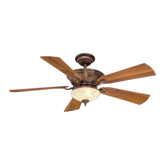
52” Bercello Estates II Thank you for purchasing our ceiling fan. This product has been manufactured with the highest standards of safety and quality. Ceiling Fan by Hampton Bay Date Purchased Table of Contents Store Purchased Safety Rules ....1 120-066 UL Model No. -
Page 4: Safety Rules
Safety Rules - Read and Save These Instructions To reduce the risk of electric shock, insure electricity has been turned off After making electrical connections, spliced conductors should be turned at the circuit breaker or fuse box before beginning. upward and pushed carefully up into outlet box. The wires should be spread apart with the grounded conductor and the equipment-grounding All wiring must be in accordance with the National Electrical Code conductor on one side of the outlet box and ungrounded conductor on the... -
Page 5: Unpacking Your Fan
Unpacking Your Fan Unpack your fan and check the contents. You should have the following items: Set of blades (5) Mounting plate Blade Attachment Hardware 3/16"×7.5mm Screws (16PCs.) Canopy assembly Light kit Ball/downrod assembly Glass shade Electrical Hardware Coupling cover Receiver+6 wire nuts Plastic Wire Nuts (3PCs.) Fan motor assembly... -
Page 6: Installing Your Fan
Installing Your Fan Provide Strong Support Tools Required Figures 1~3 are examples of different ways to mount the outlet box. Phillips screwdriver, straight slot screwdriver, step ladder and wire cutters. Recessed Ceiling Outlet Box Mounting Plate Mounting Options Figure 3 Outlet Box Note: You may need a longer downrod to If there isn't an existing UL listed mounting box,... - Page 7 Hanging the Fan WARNING Cross Pin FAILURE TO PROPERLY INSTALL COTTER PIN AS NOTED IN STEP 5 COULD RESULT IN FAN REMEMBER to turn off the power. Follow the Hanger Ball LOOSENING AND POSSIBLY FALLING. steps below to hang your fan properly. Downrod Remove the canopy cover from the canopy by turning the cover counter clockwise.
-
Page 8: Installing Fan To The Electrical Box
Installing Fan to Slip coupling cover, canopy cover and canopy UL Listed Outlet Box onto downrod. Carefully reinstall hanger ball the Electrical Box onto rod being sure that cross pin is in correct position, set screws are tighten and wires are not twisted. -
Page 9: Making The Electrical Connections
Making the Electrical receiver. Secure the wire connections with the plastic wire connecting nuts provided. Connections Frequency Switch (Figure 14) Receiver to house supply wires electrical connections: Connect the black (hot) WARNING wire from the ceiling to the black wire marked TO AVOID POSSIBLE ELECTRICAL SHOCK, BE "AC in L"... - Page 10 WARNING WARNING SUPPLY CIRCUIT MAKE SURE THE TAB ON THE HANGING CHECK TO SEE THAT ALL CONNECTIONS ARE BRACKET PROPERLY SITS IN THE GROOVE IN TIGHT, INCLUDING GROUND, AND THAT NO THE HANGER BALL BEFORE ATTACHING THE BARE WIRE IS VISIBLE AT THE WIRE NUTS. Ground EXCEPT FOR THE GROUND WIRE.
-
Page 11: Attaching The Fan Blades
WARNING Attaching the Fan Blades TO REDUCE THE RISK OF PERSONAL INJURY, DO NOT BEND THE BLADE HOLDERS WHILE Attach the fan blades to the blade holders using INSTALLING, BALANCING THE BLADES, OR Touching Ceiling CLEANING THE FAN. DO NO INSERT FOREIGN the screws provided, tighten screws securely. -
Page 12: Installing The Light Kit
Installing the Light Kit Installing the Mounting Plate CAUTION Raise the glass shade to the light kit and secure BEFORE STARTING INSTALLATION, DISCON- tightly with the decorative nut. DO NOT Remove 1 of the 3 screws from the mounting NECT THE POWER BY TURNING OFF THE OVERTIGHTEN. -
Page 13: Operating Your Transmitter
Operating Your Transmitter Installing the Battery: Restore power to the ceiling fan and test for proper operation. Install 12V MN21/A23 battery (not included), to "HI, MED, LOW" buttons: prevent damage to transmitter, remove the battery These three buttons are used to set the fan if not used for long periods. - Page 14 Speed settings for warm or cool weather depend on factors such as the room size, ceiling height, number of fans, etc. The Reverse switch is located on the top of motor housing. Slide the switch to the Left for warm weather operation.
-
Page 15: Care Of Your Fan
Remote control Do not connect the fan with a wall mounted variable speed control(s). Make sure the dip switches are set correctly. THE HAMPTON BAY FAN & LIGHTING CO. WARNING P. O. Box 395 MAKE SURE THE POWER IS OFF AT THE ELECTRICAL PANEL BOX Norco, CA 92860 BEFORE YOU ATTEMPY ANY REPAIRS. -
Page 16: Specifications
Specifications FAN SIZE SPEED VOLTS AMPS WATTS N.W. G.W. C.F. 0.29 1790 13.65 kgs 15.17 kgs 52" MED. 0.46 3895 2.25' (30.09 lbs) (33.44 lbs) 0.59 6206 HIGH These are approximate measures. They do not include Amps and Wattage used by the light kit. Distributed by Home Depot U.S.A., Inc. -
Page 17: Warranty Information
Lifetime Limited Warranty (lifetime warranty on motor) The Hampton Bay warrants the fan motor to be free from defects in workmanship and material present at time You must present a copy of the original purchase receipt to obtain warranty of shipment from the factory for a period of lifetime after the date of purchase by the original purchaser.
Need help?
Do you have a question about the Bercello Estates II and is the answer not in the manual?
Questions and answers