
Related Manuals for HAMPTON BAY Brookedale


Summary of Contents for HAMPTON BAY Brookedale
- Page 1 247 008 Brookedale Ceiling Fan Owner’s Manual Brookedale Ventilador de Techo de 1,52 Manual del Propietario...
- Page 2 Brookedale by Hampton Bay ®...
-
Page 3: Table Of Contents
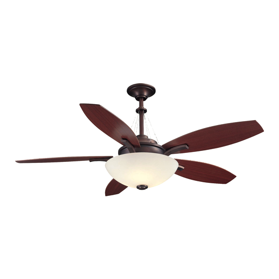
60” Brookedale Thank you for purchasing our ceiling fan. This product has been manufactured with the highest standards of safety and quality. Ceiling Fan by Hampton Bay Date Purchased Table of Contents Store Purchased Safety Rules ....1 247-008 UL Model No. -
Page 4: Safety Rules
Safety Rules - Read and Save These Instructions To reduce the risk of electric shock, insure electricity has been turned off After making electrical connections, spliced conductors should be turned at the circuit breaker or fuse box before beginning. upward and pushed carefully up into outlet box. The wires should be spread apart with the grounded conductor and the equipment-grounding All wiring must be in accordance with the National Electrical Code conductor on one side of the outlet box and ungrounded conductor on the... -
Page 5: Unpacking Your Fan
Unpacking Your Fan Unpack your fan and check the contents. You should have the following items: Set of blades (5) Fan motor assembly Blade Attachment Hardware (16 Screws with Fiber Washers) Canopy assembly Blade arms (5) Ball/downrod assembly (1) Mounting plate Electrical Hardware &... -
Page 6: Installing Your Fan
Installing Your Fan Tools Required Figures 1~3 are examples of different ways to heavy duty fan brace as shown in Figure 2 mount the outlet box. (available at any Home Depot store). Phillips screwdriver, straight slot screwdriver, step ladder and wire cutters. Provide Strong Support Mounting Options Recessed... -
Page 7: Hanging The Fan
Hanging the Fan downrod. Be careful not to jam the clevis pin Motor Wires against the wiring inside the downrod. Insert Ball/Downrod REMEMBER to turn off the power. Follow the the cotter pin through the hole near the end of Assembly the clevis pin until it snaps into its locked steps below to hang your fan properly. -
Page 8: Changing The Downrod
Changing the Downrod (Optional) Set Screw NOTE: Your fan comes with a 12" downrod attached to the hanger ball. In addition you have been provided with a 4-1/2" downrod to use if Decorative desired. If you choose to use the 4-1/2" downrod, Cable perform the following steps: Remove the hanger ball from the 12"... - Page 9 Installing Fan to the UL Listed Electrical Box Outlet Box WARNING Posts in the 120V Outlet Box Wires Ceiling TO REDUCE THE RISK OF FIRE, ELECTRIC Safety Cable SHOCK OTHER PERSONAL INJURY. Mounting MOUNT FAN ONLY TO AN OUTLET BOX OR Bracket Ceiling SUPPORTING SYSTEM MARKED ACCEPTABLE...
- Page 10 Making the Electrical WARNING SUPPLY CIRCUIT CHECK TO SEE THAT ALL CONNECTIONS ARE Connections TIGHT, INCLUDING GROUND, AND THAT NO BARE WIRE IS VISIBLE AT THE WIRE NUTS. Ground EXCEPT FOR THE GROUND WIRE. REMEMBER to disconnect the power. Conductor WARNING If you feel you do not have enough electrical Outlet Box...
-
Page 11: Attaching The Fan Blades
Finishing the Fan Screws with Outlet Box Installation Fiber Washers Ceiling Mounting Bracket Tuck connections neatly into ceiling outlet Screw box. Slide the canopy up to mounting bracket and Canopy place the key hole on the canopy over the Blade Arm screw on the mounting bracket, turn canopy Blade Screw... -
Page 12: Blade Balancing
Blade Balancing The following procedure should correct most fan wobble. Check after each step. Touching Ceiling Check that all blade and blade bracket screws are secure. Most fan wobble problems are caused when blade levels are unequal. Check this level by selecting a point on the ceiling above the tip of one of the blades. -
Page 13: Installing The Light Kit
Installing the Light Kit NOTE Carefully push all wires back into the mount- BEFORE STARTING INSTALLATION, DISCON- ing plate, then install the light kit onto the NECT THE POWER BY TURNING OFF THE mounting ring with 3 screws provided. Be sure CIRCUIT BREAKER OR REMOVING THE FUSE to tighten all screws. -
Page 14: Operating Your Transmitter
Operating Your Transmitter Installing the Battery: The receiver frequency selector is located on Bulbs the top of the motor assembly plate as shown in Install 12V MN21/A23 battery (included), to Fig. 17. prevent damage to transmitter, remove the battery The transmitter frequency selector is located in if not used for long periods. - Page 15 Restore power to the ceiling fan and test for proper operation. "HI, MED, LOW" buttons: These three buttons are used to set the fan speed as follows: LOW=Low speed, MED= Medium speed HI=High speed "OFF" button: This button turns the fan off. Figure 19 Figure 20 NOTE...
-
Page 16: Care Of Your Fan
Care of Your Fan Troubleshooting PROBLEM SOLUTION Here are some suggestions to help you maintain your fan. Fan will not start Check main and branch circuit fuses or breakers. Because of the fan's natural movement, some Check line wire connections to the fan and switch wire connections in the connections may become loose. -
Page 17: Specifications
Specifications FAN SIZE SPEED VOLTS AMPS WATTS N.W. G.W. C.F. 0.40 2948 15.58 kgs 18.72 kgs 60” MED. 0.58 4902 4.45’ (34.37 lbs) (41.30 lbs) HIGH 0.72 6657 These are approximate measures. They do not include Amps and Wattage used by the light kit. -
Page 18: Warranty Information
Hampton Bay Lifetime Limited Warranty (lifetime warranty on motor) The Hampton Bay warrants the fan motor to be free from defects in workmanship and material present at time You must present a copy of the original purchase receipt to obtain warranty of shipment from the factory for a period of lifetime after the date of purchase by the original purchaser.
Need help?
Do you have a question about the Brookedale and is the answer not in the manual?
Questions and answers
I lost the remote, how do I get a replacement? Model AC-418, SN 001654