
Related Manuals for Tysso PRP-080SC


Summary of Contents for Tysso PRP-080SC
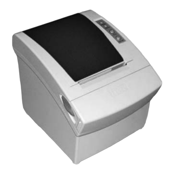
- Page 1 User's Manual PRP-080 THERMAL RECEIPT PRINTER Specifications subjects to change without notice...
-
Page 2: Table Of Contents
Contents 1. General Information ............2 2. Quick Start 2.1) Unpacking & Parts Identification......3 2.2) Loading the Paper Roll ..........4 3. Printer Interface and Connection 3.1) Connecting the Interface Cable ......... 6 3.2) Connecting to a Cash Drawer ........6 3.3) Connecting the AC Adapter ........7 4. -
Page 3: General Information
1. General Information 2. Quick Start Models 2.1) Unpacking & Parts Identification a. Inside the Package: PRP-080SC (serial interface, with auto-cutter) PRP-080PC (parallel interface, with auto-cutter) PRP-080SN (serial interface, without auto-cutter) PRP-080PN (parallel interface, without auto-cutter) Main Features 1. High speed printing: 220mm/s maximum print speed. -
Page 4: Loading The Paper Roll
c. While observing the direction of the roll, set the paper roll 2.2) Loading the Paper Roll into the hollow, and pull out the leading edge of the paper a. Make sure that the paper roll matches the printer's toward you as shown: specification. -
Page 5: Printer Interface And Connection
Printer Interface and Connection 3.1) Connecting the Interface Cable 3.3) Connecting the AC Adapter a. Before connecting/disconnecting the interface cable, a. Connect the AC power cord to the inlet of AC adapter, make sure that power to the printer and all the devices and then connect the power cord plug to a suitable connected to the printer is turned off. -
Page 6: Configuration
4. Configuration Printer Control Panel & Status Indication 4.2) DIP Switch Settings The DIP switch panel is located at bottom of the printer as shown: (Blue LED) The POWER light is on whenever DIP Switch Functions: the printer is on. Switch Function Default (Red LED) This indicates printer online/offline... -
Page 7: Safety And Maintenance
5. Safety and Maintenance 5.1) Safety Information 5.2) Periodical Cleaning Printed characters may become partially unclear due to 1. Do not touch the HEAD of printer with anything. accumulated paper dust and dirt. To prevent such a problem, 2. Do not touch the cutter blade. paper dust collected in the paper holder and paper transport 3. -
Page 8: Fixing Paper Jam
5.4) Fixing Paper Jam The Status LED (Red) on the printer control panel will flash e. Return the cutter to its home-position and release or clean with beeps if paper is jammed. Please follow the below out the jammed paper inside the front cover. Open the instruction to remove paper jam. -
Page 9: Appendix (A) Specifications
Appendix (A) Specifications Power supply Print method Direct thermal Max. label width Input 100V AC ~ 240V AC, 50 ~ 60 Hz 79.5mm 0.5mm Output +24V DC/2.5A Character per line 48 (Font A)Effective print width Print font 72mm Print speed 220mm/sec.(max.) or 58 lines/sec. -
Page 10: Appendix (B) Configurations
Appendix (B) Configurations 1. Interface 1.1.2 Switching between on-line and off-line The printer has an on-line/off-line button. 1.1 RS-232 serial interface The printer goes off-line: 1.1.1 RS-232 Specifications Between when the power is turned on (including reset Data transmission: Serial using the interface) and when the printer is ready to Synchronization: Asynchronous... -
Page 11: Ieee 1284 Bidirectional Parallel Interface
Source Compatibility Nibble Mode Byte Mode 1.2 IEEE 1284 Bidirectional Parallel Interface Mode (Parallel Interface Specifications) Printer nFault nDataAvail/Data0, 4 nDataAvail Copyright (C) 1993 by the Institute of Electrical and Electronic Engineers, Inc. Printer DK_STATUS Interface Pin Assignments for Each Mode Printer Source Compatibility... -
Page 12: Appendix (C) Commands List
Appendix (C) Commands List Drawer Kick-out Connector Pin Assignments Command Name Horizontal tab Pin Number Signal Name Direction Print and line feed Frame GND Print and carriage return ESC SP n Set right-side character spacing ESC ! N Select print mode(s) ESC $ nL nH Set absolute print position Drawer kick-out drive signal Output...
Need help?
Do you have a question about the PRP-080SC and is the answer not in the manual?
Questions and answers