Table of Contents
Advertisement
Quick Links
OPERATOR'S MANUAL
INCLUDING: OPERATION, INSTALLATION & MAINTENANCE
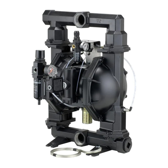
2" DRY POWDER DIAPHRAGM PUMP
It is the responsibility of the employer to place this information in the hands of the operator. Keep for future reference.
Refer to Model Description Chart to match the pump mate-
rial options.
7102 valve kit for repair of H254PS control valve.
104255 for repair of P29122-100 fi lter / regulator.
118597-002 spool kit for repair of A212PD 4-way alpha valve.
637309-XX for fl uid section repair (see page 6). NOTE: This kit
also contains several air motor seals which will need to be
replaced.
637421 for air section repair (see page 8).
PUMP DATA
Models . . . . . . . . . . . . . see Model Description Chart for "-XXX"
Pump Type . . . . . . . . . Metallic, Dry Powder, Diaphragm Pump
Material . . . . . . . . . . . . see Model Description Chart
Specifi c Application for pumping powders up to 50 lb. / ft
Weight . . . PP20A-XAX-XXX . . . . . . . . . . 99.4 lbs (45.1 kgs)
PP20A-XSX-XXX . . . . . . . . . . 157.8 lbs (71.6 kgs)
Maximum Air Inlet Pressure . . . . . . . . 50 p.s.i.g. (3.4 bar)
Maximum Fluidizing Pressure . . . . . . 100 p.s.i.g. (6.9 bar)
Maximum Particle Size . . . . . . . . . . . . . 1/4" dia. (6.4 mm)
Maximum Temperature Limits (diaphragm / ball / seal
materials)
Nitrile . . . . . . . . . . . . . . . . . . . . 10° to 180° F (-12° to 82° C)
Santoprene® . . . . . . . . . . . . . . -40° to 225° F (-40° to 107° C)
Dimensional Data . . . . . . . . . . . . . . . . . . . see page 12
Mounting Dimension . 9-1/16" x 10-1/16" (230 mm x 256 mm)
Noise Level @ 70 p.s.i., 50 c.p.m. . . . . 83.0 db(A)
Tested with 94085 muffl er assembly installed.
The pump sound pressure levels published here have been updated to
an Equivalent Continuous Sound Level (L
S1.13-1971, CAGI-PNEUROP S5.1 using four microphone locations.
NOTICE: All possible options are shown in the chart, however, certain
combinations may not be recommended. Consult a representative or
the factory if you have questions concerning availability.
INGERSOLL RAND COMPANY LTD
209 NORTH MAIN STREET - BRYAN, OHIO 43506
(800) 495-0276 FAX(800) 892-6276
www.ingersollrandproducts.com
1:1 RATIO (METALLIC)
READ THIS MANUAL CAREFULLY BEFORE INSTALLING,
OPERATING OR SERVICING THIS EQUIPMENT.
3
) to meet the intent of ANSI
Aeq
© 2010
CCN 15235526
PP20A-XXX-XXX Powder Pump
MODEL DESCRIPTION CHART
Fluid Connection
B - 2 - 11 BSP
C - 2-1/2" Tri-Clamp
Fluid Cap & Manifold Material
A - Aluminum
S - Stainless Steel
Hardware Material
P - Plated Steel
S - Stainless Steel
Seat Material
A - Santoprene
S - Stainless Steel
Ball Material
A - Santoprene
M - Medical Grade Santoprene
Diaphragm Material
A - Santoprene
M - Medical Grade Santoprene
Fluid Section Service Kit Selection
EXAMPLE: Model #PP20A-AAS-AAA
Fluid Section Service Kit # 637309-AA
RELEASED:
6-2-05
REVISED:
6-21-10
(REV. 04)
Figure 1
PP20A - X X X - X X X
PP20A - XXX - X X X
637309 - X X
Ball
Diaphragm
Advertisement
Table of Contents

Related Manuals for Ingersoll-Rand PP20A-XXX-XXX


Summary of Contents for Ingersoll-Rand PP20A-XXX-XXX
-
Page 1: Table Of Contents
(800) 495-0276 FAX(800) 892-6276 © 2010 www.ingersollrandproducts.com PP20A-XXX-XXX 1:1 RATIO (METALLIC) OPERATING OR SERVICING THIS EQUIPMENT. PP20A-XXX-XXX Powder Pump PP20A-XAX-XXX MODEL DESCRIPTION CHART Fluid Connection A - 2 - 11-1/2 N.P.T.F. - 1 B - 2 - 11 BSP C - 2-1/2” Tri-Clamp Fluid Cap &... -
Page 2: Operating And Safety Precautions
= Hazards or unsafe practices which WARNING could result in severe personal injury, death or substantial property damage. = Hazards or unsafe practices which CAUTION could result in minor personal injury, product or property damage. = Important installation, operation or NOTICE maintenance information. PP20A-XXX-XXX (en) -
Page 3: General Description
The material inlet supply tubing should not be too PP20A-XXX-XXX (en) small or restrictive, which will inhibit material flow. The outlet material volume is governed not only by the air supply, but also by the material volume available at the inlet. -
Page 4: Trouble Shooting
Loctite® and 242® are registered trademarks of Henkel Loctite Corporation ARO® is a registered trademark of Ingersoll-Rand Company Santoprene® is a registered trademark of Monsanto Company, licensed to Advanced Elastomer Systems, L.P. 271™ is a trademark of Henkel Loctite Corporation Lubriplate®... -
Page 5: Typical Cross Section
TYPICAL CROSS SECTION Figure 3 PP20A-XXX-XXX (en) Page 5 of 12... -
Page 6: Service Kits
-XX = (Ball) -XXX -XX = (Diaphragm) Diaphragm Qty [Mtl] “O” Ring -XXA 637309-XA 94329-A -XXM 637309-XM 94329-M MANIFOLD CONNECTION / FLUID CAP MATERIAL OPTIONS PP20A-XXX-XXX Item Description Qty Part No. (size) 6 Diaphragm Washer (2) 96503 15 Fluid Cap... -
Page 7: Torque Requirements
PARTS LIST / PP20A-XXX-XXX FLUID SECTION TORQUE REQUIREMENTS NOTE: DO NOT OVERTIGHTEN FASTENERS. (14) diaphragm screws, 65 - 70 ft lbs (88.1 - 94.9 Nm). (26) screws, 30 - 40 ft lbs (40.7 - 54.2 Nm). (27) screws, 30 - 40 ft lbs (40.7 - 54.2 Nm). - Page 8 PARTS LIST / PP20A-XXX-XXX AIR MOTOR SECTION Indicates parts included in 637421 air section repair kit, plus items 70, 144, 175 and 180 (page 6). Item Description (Qty) Part No. (size) 101 Center Body (1) 94028 103 Bushing (1) 95955...
- Page 9 PARTS LIST / PP20A-XXX-XXX AIR MOTOR SECTION MAJOR VALVE PP20A-XXX-XXX (en) TORQUE REQUIREMENTS NOTE: DO NOT OVERTIGHTEN FASTENERS. ALL FASTENERS ARE METRIC. (105) screw, 40 - 50 in. lbs (4.5 - 5.6 Nm). (134) screw, 40 - 50 in. lbs (4.5 - 5.6 Nm).
- Page 10 PARTS LIST / PP20A-XXX-XXX CONTROL SECTION Item Description (size) 76 Adapter (1/8 - 27 N.P.T.F. - 1) 77 Elbow (1/4” o.d. tube x 1/8 - 27 N.P.T.) 78 Tube (1/4” o.d. x 14”) 245 Air Line Connection Kit (not shown) 246 Adapter (1/8 N.P.T.F.
- Page 11 PARTS LIST / PP20A-XXX-XXX CONTROL SECTION See view “A-A” (14” long) (7.5” long) (27” long) Page 11 of 12 (2” long) (9” long) (14” long) Figure 7 PP20A-XXX-XXX (en)
-
Page 12: Dimensional Data
(outlet this side) L - see below M - see below N - see below "M" "N" 14-5/8" (371.2 mm) 20-5/32" (512.0 mm) 15-1/4" (387.1 mm) 20-25/32" (527.8 mm) 15-1/4" (387.1 mm) 20-25/32" (527.8 mm) Figure 8 PN 97999-1136 PP20A-XXX-XXX (en)
Need help?
Do you have a question about the PP20A-XXX-XXX and is the answer not in the manual?
Questions and answers