Table of Contents
Advertisement
Advertisement
Table of Contents

Related Manuals for Fujitsu D943


Summary of Contents for Fujitsu D943
- Page 1 System board D943 Technical Manual...
- Page 2 Is there ..any technical problem or other ... anything you want to tell us question you need clarified? about this manual? Please contact: Please send us your comments quoting • one of our IT Service Shops the order number of the manual. •...
- Page 4 Questo manuale è stato stampato su carta da riciclaggio. Denna handbok är tryckt på recyclingpapper. Dit handboek werd op recycling-papier gedrukt. Herausgegeben von/Published by Siemens Nixdorf Informationssysteme AG D-33094 Paderborn D-81730 München Bestell-Nr./Order No.: A26361-D943-Z120-14-7619 A26361-D943-Z120-14-7619 A26361-D943-Z120-14-7619 A26361-D943-Z120-14-7619 Printed in the Federal Republic of Germany AG 0298 02/98...
- Page 5 Introduction Important notes System board D943 Settings in BIOS Setup Settings with switch block S180 Add-on modules Technical Manual Error messages Index February 1998 edition...
- Page 6 Your training needs? The Siemens Nixdorf Training Centers offer you a wide range of training courses in information technology and on IT products and other subjects - onsite near to your workplace or offsite at one of our training centers. Contact us for information on consulting, course schedules and selfstudy material - Either fax (which is the fastest way): Fax: ..49 89 636-42945...
-
Page 7: Table Of Contents
............... 33 Set Setup Password ..................34 Setup Password Lock ..................34 Set System Password..................34 System Password Mode ................. 35 System Load....................35 Setup Prompt- Setup message ................ 35 Virus Warning....................36 Diskette Write ....................36 Flash Write..................... 36 A26361-D943-Z120-14-7619... - Page 8 ................52 Removing a memory module................52 Replacing the processor..................53 Upgrading the second-level cache ................. 54 Upgrading the video memory ................54 Connecting an audio board ..................56 Replacing the lithium battery................. 57 Error messages..................... 59 Index ........................61 A26361-D943-Z120-14-7619...
-
Page 9: Introduction
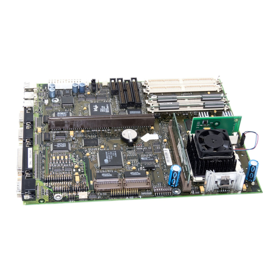
Introduction This description applies for the System board D943 with PCI bus (Peripheral Component Interconnect). This system board is available in different configuration levels. Depending on the hardware configuration of your device, it may be that you cannot find several options in your version of the system board, even though they are described. -
Page 10: Features
Floppy disk controller (up to 2.88 Mbytes format) • Bus interface for platter • Connector for feature connector, loudspeaker • Parallel interface (ECP- and EPP-compatible) • 2 serial ports • PS/2 mouse port • PS/2 keyboard port • Security functions A26361-D943-Z120-14-7619... - Page 11 Microphone connector (via supplementary board) • Audio port (line in) (via supplementary board) • Headphone connector (via supplementary board) The microphone connector, audio port and headphone connector are connected via a common plug (Game/Midi / Audio) on the system board. A26361-D943-Z120-14-7619...
-
Page 12: Interfaces And Connectors
12 = infrared interface 26 = AUX IN 13 = Remote on via fax/modem 27 = Voice modem 14 = Chipcard reader 28 = Game/Midi/Audio 29 = Wavetable board The connectors marked do not have to be present on the system board. A26361-D943-Z120-14-7619... -
Page 13: Possible Screen Resolution
Operating Manual or Technical Manual supplied with the controller. You can set the screen resolution under Windows 95 by selecting Control Panel - Display - Settings . You can set the screen resolution under MS-DOS using the program. SET-VGA A26361-D943-Z120-14-7619... - Page 14 1280x1024 80,4 256 * no 16 color mode The horizontal rate values may have a tolerance range of ± 0.3 kHz. not for graphics processor Cirrus Logic CL-GD5446 The values marked are only available with a 2-Mbytes video memory. A26361-D943-Z120-14-7619...
-
Page 15: Resource Table
„Possible address“ = this address can be used for your particular application „Possible DMA“ = this DMA can be used for your particular application Please note that a resource cannot be used by two applications at the same time. A26361-D943-Z120-14-7619... -
Page 17: Important Notes
There is a danger of burns! The warranty expires if the device is damaged during the installation or replacement of system expansions. Information on which system expansions you can use is available from your sales office or the customer service. A26361-D943-Z120-14-7619... - Page 18 The equipment and tools you use must be free of static charges. • Pull out the power plug before inserting or pulling out boards containing ESDs. • Always hold boards with ESDs by their edges. • Never touch pins or conductors on boards fitted with ESDs. A26361-D943-Z120-14-7619...
-
Page 19: Settings In Bios Setup
Floppy disk drive (in the field marked Diskette A Diskette B • Hard disk drive (in the submenus of Hard Disk • Display device (in the field marked Video Display • System boot (in the submenus of Boot Options A26361-D943-Z120-14-7619... -
Page 20: System Time / System Date
360K, 720K, 1.2M, 1.4M 2.8M The entry depends on the floppy disk drive installed. (Default entry Diskette A : 1.4M (Default entry Diskette A : 1.4M A floppy disk drive is not installed. None (Default entry for Diskette B:). A26361-D943-Z120-14-7619... -
Page 21: Hard Disk 1 To Hard Disk 4 - Hard Disk Drives
LBA Translation: [Enabled] PIO Mode: [Fast PIO 3] 32 Bit I/O: [Enabled] ↑↓ Help Select Item Change Values F9 Setup Defaults ← → ESC Exit Select Menu Enter Execute Command F7 Previous Values Hard Disk Example for the submenu A26361-D943-Z120-14-7619... - Page 22 Hard disk hard disk capacity parameter 850 Mbyte 1,2 Gbyte 1,6 Gbyte Cylinders 1654 2484 3148 Heads Sectors Write Precomp None None None If an ATAPI CD-ROM drive is installed, this entry enables you to boot from the CD-ROM drive. A26361-D943-Z120-14-7619...
- Page 23 This allows the disk's full capacity to be used. If the hard disk does not support LBA, its parameters are not translated. The BIOS uses the hard disk parameters and supports a maximum Disabled capacity of 528 Mbytes. A26361-D943-Z120-14-7619...
-
Page 24: Boot Options
Quiet Boot: [Disabled] Boot Sequence: 1. Diskette 2. Hard Disk 3. CD ROM ↑↓ Help Select Item Change Values F9 Setup Defaults ← → ESC Exit Select Menu Enter Execute Command F7 Previous Values Boot Options Example for submenu A26361-D943-Z120-14-7619... - Page 25 The logo is displayed on the screen. A switch to the start Enabled information is made if you press the key or if errors occur. [Esc] [Esc] [Esc] [Esc] The start information is displayed on the screen (default entry). Disabled A26361-D943-Z120-14-7619...
-
Page 26: Video Display
This field is used to specify the type of monitor connected. EGA/VGA, Color 80, Monochrome Default entry: EGA/VGA Base Memory This field indicates the size of the available base memory below 1 Mbyte. Extended Memory indicates the size of the memory above 1 Mbyte. A26361-D943-Z120-14-7619... -
Page 27: Advanced Menu - Making Advanced System Settings
Plug & Play O/S: [Yes] Reset Configuration Data: [No] Large Disk Access Mode: [DOS] ↑↓ Help Select Item Change Values F9 Setup Defaults ← → ESC Exit Select Menu Enter Execute Command F7 Previous Values Advanced Example for the menu A26361-D943-Z120-14-7619... -
Page 28: Cache Memory
Internal (first-level cache) and external cache (second-level cache) are enabled. If there is no external Cache, only the internal cache is used. Internal (first-level cache) and external cache (second-level cache) Disabled are disabled. All cache-related settings are then without effect. A26361-D943-Z120-14-7619... - Page 29 The relevant ROM area is mapped to the cache. Enabled The relevant ROM area is not mapped to the cache (default entry). Disabled If your ISA board uses a dual ported RAM in the associated ROM area, set the entry to Disabled A26361-D943-Z120-14-7619...
-
Page 30: Shadow Memory
BIOS to fast RAM increases system performance. The video BIOS is copied to fast RAM (default entry). Enabled The video BIOS is not copied to fast RAM. This setting is not Disabled effective with an external screen controller connected to the PCI bus. A26361-D943-Z120-14-7619... -
Page 31: Peripheral Configuration - Ports And Controllers
Hard Disk Controller: [Primary And Secondary] Mouse Controller: [Enabled] Audio Controller: [Enabled] USB Controller: [Disabled] ↑↓ Help Select Item Change Values F9 Setup Defaults ← → ESC Exit Select Menu Enter Execute Command F7 Previous Values Peripheral Configuration Example for submenu A26361-D943-Z120-14-7619... - Page 32 378h, IRQ7 278h, IRQ5 3BCh, IRQ7 The parallel port is set to the shown address and interrupt. The parallel interface is automatically set to the next available Auto combination (address, interrupt) (Default entry). The parallel interface is disabled. Disabled A26361-D943-Z120-14-7619...
- Page 33 This field allows you to enable and disable the built-in IDE hard disk controller. The associated interrupts (IRQ 14 for the first connector, IRQ 15 for the second connector) will only be available if no IDE hard disk drive is physically connected. A26361-D943-Z120-14-7619...
- Page 34 The audio controller is disabled. Disabled USB Controller switches the USB controller (Universal Serial Bus) of the system board on or off. The system BIOS determines which system resources (interrupts, Enabled addresses) are occupied. The USB controller is disabled (default entry). Disabled A26361-D943-Z120-14-7619...
-
Page 35: Pci Configuration
Latency Timer: [0040] PCI Device, Slot #3 Default Latency Timer: [Yes] Latency Timer: [0040] ↑↓ Help Select Item Change Values F9 Setup Defaults ← → ESC Exit Select Menu Enter Execute Command F7 Previous Values Example for submenu PCI Configuration A26361-D943-Z120-14-7619... - Page 36 , IRQ9 is assigned. PCI Interrupt Mapping The interrupt is assigned to the screen controller on the built-in Enabled PCI board (default entry). The interrupt can be used for other add-on boards. Disabled A26361-D943-Z120-14-7619...
-
Page 37: Advanced System Configuration
Memory Performance: [Fast] Cache Performance: [Fast] Memory Current: [8mA] Feature Connector: [Disabled] ↑↓ Help Select Item Change Values F9 Setup Defaults ← → ESC Exit Select Menu Enter Execute Command F7 Previous Values Advanced System Configuration Example for submenu A26361-D943-Z120-14-7619... - Page 38 Feature Connector - Enabling of Feature Connectors This field is used to enable and disable the feature connector on the system board. The feature connector is enabled. Enabled The feature connector is disabled (default entry). Disabled A26361-D943-Z120-14-7619...
-
Page 39: Plug & Play O/S
Plug&Play. The operating system takes over some of the Plug&Play functions. You should select this setting only if the operating system supports Plug&Play. The BIOS takes over the complete Plug&Play functionality (default setting). A26361-D943-Z120-14-7619... -
Page 40: Reset Configuration Data
(more than 1024 cylinders, 16 heads). The default setting depends on the operating system used. the operating system uses MS-DOS-compatible hard disk accesses. If the operating system uses hard disk accesses which are not MS- Other DOS-compatible (e.g. Novell, SCO Unix). A26361-D943-Z120-14-7619... -
Page 41: Menu Security - Setting Up The Security Features
Select Item Change Values F9 Setup Defaults ← → ESC Exit Select Menu Enter Execute Command F7 Previous Values Security Example for menu Setup Password / System Password These fields indicate whether the appropriate password is installed or not. A26361-D943-Z120-14-7619... -
Page 42: Set Setup Password
This field enables you to install the system password. The system password prevents unauthorized access to your system. Mark the field and press the Return key. You can then enter and confirm the system password (see also the PC Operating Manual). A26361-D943-Z120-14-7619... -
Page 43: System Password Mode
Press F2 to enter SETUP when the system is rebooted. The setup message is displayed Enabled Press F2 to enter SETUP when the system is started (default entry). The setup message is not displayed. Disabled A26361-D943-Z120-14-7619... -
Page 44: Virus Warning
System BIOS is disabled in the BIOS setup (switch 5 = BIOS update from floppy disk is possible (default entry). The System BIOS can neither be written to nor deleted. BIOS Disabled update from floppy disk is not possible A26361-D943-Z120-14-7619... -
Page 45: Power On/Off
( DeskOff, SWOFF or an operating system ( Windows 95, Windows NT with Siemens Nixdorf HAL The system can be switched off with the program (default Enabled SWOFF entry). The system cannot be switched off with a program. Disabled A26361-D943-Z120-14-7619... - Page 46 The system can be switched on using a special on/off button on the Enabled keyboard (default entry). The system cannot be switched on using a special on/off button on Disabled the keyboard. A26361-D943-Z120-14-7619...
- Page 47 Server Chipcard specifies whether the system can be switched on via the chipcard reader. The system can be switched on via the chipcard reader (default). Enabled (Default entry.) The system cannot be switched on via the chipcard reader. Disabled A26361-D943-Z120-14-7619...
-
Page 48: Power Menu - Setting Energy Saving Functions
Determines whether an operation system can change the power management settings in the system BIOS. The operating system has access to the power management settings Enabled and can change these if necessary (default entry). Changes can not be made to power management setting by an Disabled operating system. A26361-D943-Z120-14-7619... -
Page 49: Power Management Mode - Extent Of Energy Saving Functions
Suspend Timeout will be aborted. 2 min 15 min 30 min 1 Std 2 Std 3 Std 4 Std Default entry = 15 min The PC does not switch to suspend mode Disabled A26361-D943-Z120-14-7619... -
Page 50: Hard Disk Timeout
This system status is restored when you restart the system; in other words, you can carry on working in the same application. The contents of the main memory, working memory, video Enabled memory and cache are saved to the hard disk. The memory contents are not saved (default entry). Disabled A26361-D943-Z120-14-7619... - Page 51 SCSI controllers and graphics controllers. These restrictions also apply if you activate the function (Save Quickstart to disk) under Windows using DeskEnergy Before starting the function, you should first close all Save to Disk documents located on network drives. A26361-D943-Z120-14-7619...
-
Page 52: Wakeup Event - Defining System Activities
Enter Select Ê Sub-Menu ESC Exit Select Menu F7 Previous Values Wakeup Event Example for submenu The associated interrupt is evaluated as a system activity. Enabled The associated interrupt has no effect on the active energy saving Disabled mode. A26361-D943-Z120-14-7619... -
Page 53: Biosfax Menu - Quick Start Functions
Modem functionality is not available when the system is switched Disabled off (default entry). Ring Count Defines how often a ring tone should sound before the modem answers. Possible settings: (default entry). 2, 3, 4, 5, 6, 7 Auto A26361-D943-Z120-14-7619... -
Page 54: Fax Tone Count
2, 3, 4, 5, 6, 7 Auto Fax Modem Port - Serial port Shows which serial interface is used for the modem. This setting is assigned by the system and cannot be changed. Possible displays: COM1 COM2 COM3 COM4 A26361-D943-Z120-14-7619... -
Page 55: Exit Menu
BIOS Setup Get Default Values reverts all settings to the default values. Load Previous Values sets the values which were in effect when BIOS Setup was called. Save Changes saves the settings you have made. A26361-D943-Z120-14-7619... -
Page 57: Settings With Switch Block S180
If you want to replace the processor, contact your sales outlet or our service center, since you may require a voltage converter. processor switch 1 switch 2 switch 3 switch 4 75 MHz 90 MHz 100 MHz 120 MHz 133 MHz 150 MHz 166 MHz 200 MHz A26361-D943-Z120-14-7619... -
Page 58: Write Protection For System Bios - Switch 5
To write and delete floppy disks, the write protection in BIOS must be disabled (in menu , the field must be set to setup Security Diskette Write Enabled The floppy disk drive is write-protected. Read, write and delete floppy disks is possible (default setting). A26361-D943-Z120-14-7619... -
Page 59: Add-On Modules
In other words, you fit the first pair to bank 0, and the second pair in bank 1. Pairs of memory modules must have the same capacity and the same access time. The ECC error identification is only possible for modules with parity checks A26361-D943-Z120-14-7619... -
Page 60: Installing Memory Modules
Removing a memory module Carefully push the retaining clips at each end of the module outwards (1). Ê Tilt the memory module forwards (2), and pull it upwards and at an angle out Ê of the mounting location (3). A26361-D943-Z120-14-7619... -
Page 61: Replacing The Processor
Set the switches 1, 2 , 3 and 4 depending on the processor which is installed. Ê If you want to replace the processor, contact your sales outlet or our service center, since you may require a voltage converter. A26361-D943-Z120-14-7619... -
Page 62: Upgrading The Second-Level Cache
Pull the second-level cache module out of the mounting location in the Ê direction of the arrow. Upgrading the video memory If your system board is supplied with a video memory configuration of 1 Mbyte, you may enlarge the video memory up to 2 Mbytes. A26361-D943-Z120-14-7619... - Page 63 Note the location of the DRAM chip when you plug in DRAM chip! Insert the DRAM component in such a way in the socket for video memory Ê that the mark on the upper side of the DRAM component (A) matches the position of the mark on the socket. A26361-D943-Z120-14-7619...
-
Page 64: Connecting An Audio Board
Game/Midi / Audio port on the system board. The plug on the connecting line is exactly the same width as the Game/Midi / Audio port. Plug the connecting line into the Game/Midi / Audio port. Ê A26361-D943-Z120-14-7619... -
Page 65: Replacing The Lithium Battery
Make sure that you insert the battery the right way round. The plus pole must be on the top! Lift the contact (1) a few millimeters and remove the battery from its socket Ê (2). Insert a new lithium battery of the same type in the socket (3). Ê A26361-D943-Z120-14-7619... -
Page 67: Error Messages
Keyboard error nn Release the key on the keyboard (nn is the hexadecimal code for the key). Monitor type does not match CMOS - RUN SETUP Correct the entry for the monitor type in the Main menu of the BIOS Setup. A26361-D943-Z120-14-7619... - Page 68 Call the BIOS Setup and correct the previously made entries or set the default entries. System timer error Switch the PC off and on again. If the message is still displayed, please contact your sales office or customer service. A26361-D943-Z120-14-7619...
-
Page 69: Index
Advanced Power Management, see APM interface Advanced System Configuration Advanced system settings APM, interface ASR&R Boot Delay Assigning PCI interrupts PCI VGA interrupts Assignment DMA channels interrupt Audio board, connecting Audio controller 3, Audio input Autotype Hard Disk 14, Available A26361-D943-Z120-14-7619... - Page 70 Menu BIOSFaX Menu Power Menu Security security functions settings system configuration write-protection BIOS Update Diskette BIOSFaX Board safety Boot Logo Boot Options Boot sector, changes Boot Sequence Boot, see also System startup Booting system 16, 17, Buswidth, setting Cache A26361-D943-Z120-14-7619...
- Page 71 Clock cycle, PCI slot Clock speed Switch Computer virus Configuration data, initializing Configuration, BIOS Setup Connecting, audio board Connector AUX-in CD line in Game/Midi Game/Midi / Audio voice modem Controller audio drive floppy disk drive mouse setting Current system status, saving A26361-D943-Z120-14-7619...
- Page 72 Effect setup password System password Energy saving Energy saving functions hard disk drive setting Energy saving mode Enhanced Capability Port, see ECP Enhanced Parallel Port, see EPP Error Correction Code, see ECC Error messages Error recognition Exit, BIOS Setup A26361-D943-Z120-14-7619...
- Page 73 Flash BIOS floppy disk write-protection Flash Write 36, Floppy disk drive type write-protection 36, Floppy disk drive controller setting Function key Functionality, switching on/off Game/Midi / Audio 4, Game/Midi, connector Get Default Values Graphics controller screen resolutions A26361-D943-Z120-14-7619...
- Page 74 IDE hard disk drive, see Hard disk drive IDE hard disk, see Hard disk Important notes Infrared interface Initializing, configuration data Installation Setup password System password Installing memory module second-level cache Internal cache first-level cache write-access Interrupt assigning serial interface Interrupt table ISA memory area A26361-D943-Z120-14-7619...
- Page 75 Loudspeaker, connector Main memory upgrading Main menu Memory base memory cache extended memory main memory 18, second-level cache video memory Memory area, ISA board Memory Current Memory module installing removing Memory performance Memory speed Menu Advanced BIOS Setup BIOSFaX Exit A26361-D943-Z120-14-7619...
- Page 76 Parallel data transfer interface 24, Parallel Mode Parameter, hard disk drive Parity check 30, Parity Mode Password Setup password System password assigning interrupts assigning VGA interrupts Configuration functionality settings PCI Device, Slot #n: PCI Interrupt Mapping INTx# A26361-D943-Z120-14-7619...
- Page 77 Power Off Source Keyboard Software Power, BIOS Setup Press F2 to enter SETUP Primary connector, drive controller Printer Processor clock speed internal cache replacing Processor clock, standby function Program, switching system off Programmed Input Output Mode, see PIO Quick boot A26361-D943-Z120-14-7619...
- Page 78 Save Changes & Exit Save To Disk SAVETO.DSK Saving current system status settings Screen resolutions Secondary connector, drive controller Second-level cache external cache setting upgrading write-access Sectors/Track, hard disk parameter Security function, BIOS Setup Selftest 16, Sequence, system startup Serial 1 A26361-D943-Z120-14-7619...
- Page 79 Setup Password Lock Setup Prompt Setup, see BIOS Setup Shadow Memory Shadow Memory Regions Software, system switching off Standby CPU Speed Standby function, processor clock Standby mode Standby Timeout Startup sequence Storage capacity, hard disk Suspend mode A26361-D943-Z120-14-7619...
- Page 80 System activities, setting System BIOS recovering write-protection 36, System board, see board System boot, see System startup System configuration, BIOS Setup System Date A26361-D943-Z120-14-7619...
- Page 81 Transfer mode 15, hard disk parallel port Transfer rate, hard disk Type of monitor Type, Hard Disk Type Update BIOS defective Upgrading Main memory second-level cache USB Controller VGA interrupt Video Display A26361-D943-Z120-14-7619...
- Page 82 Index Video memory, upgrading Video Shadow Video-BIOS Virus Warning Voice modem, connector Wakeup Event Wavetable module Write Back Write Precomp, hard disk parameter Write protection floppy disk drive 36, system BIOS 36, Write Through A26361-D943-Z120-14-7619...
Need help?
Do you have a question about the D943 and is the answer not in the manual?
Questions and answers