Table of Contents
Advertisement
Quick Links
TECHNISCHES HANDBUCH
TECHNISCHES HANDBUCH
TECHNISCHES HANDBUCH
TECHNISCHES HANDBUCH
TECHNICAL MANUAL
TECHNICAL MANUAL
TECHNICAL MANUAL
TECHNICAL MANUAL
S Y S T E M B A U G R U P P E D 1 1 5 6
S Y S T E M B A U G R U P P E
S Y S T E M B A U G R U P P E
S Y S T E M B A U G R U P P E
S Y S T E M B O A R D D 1 1 5 6
S Y S T E M B O A R D D 1 1 5 6
S Y S T E M B O A R D D 1 1 5 6
S Y S T E M B O A R D D 1 1 5 6
D 1 1 5 6
D 1 1 5 6
D 1 1 5 6
Advertisement
Table of Contents

Related Manuals for Fujitsu Siemens D1156


Summary of Contents for Fujitsu Siemens D1156
- Page 1 S Y S T E M B A U G R U P P E S Y S T E M B A U G R U P P E D 1 1 5 6 S Y S T E M B A U G R U P P E S Y S T E M B A U G R U P P E D 1 1 5 6 D 1 1 5 6...
- Page 2 • Ihre Verkaufsstelle Die Adressen Ihrer Servicepartner finden Sie im Garantieheft oder im Service-Adressenheft. Aktuelle Informationen zu unseren Produkten, Tipps, Updates usw. finden Sie im Internet: http://www.fujitsu-siemens.com Is there ..any technical problem or other question you need clarified? Please contact: •...
- Page 4 Este manual ha sido impreso sobre papel reciclado. Questo manuale è stato stampato su carta da riciclaggio. Denna handbok är tryckt på recyclingpapper. Dit handboek werd op recycling-papier gedrukt. Herausgegeben von/Published by Fujitsu Siemens Computers GmbH A26361-D1156-Z120-1-7419 A26361-D1156-Z120-1-7419 A26361-D1156-Z120-1-7419 A26361-D1156-Z120-1-7419 Bestell-Nr./Order No.:...
- Page 5 Deutsch English Systembaugruppe D1156 System Board D1156 Technisches Handbuch Technical Manual Ausgabe Januar 2000 January 2000 edition...
- Page 6 Alle weiteren genannten Warenzeichen sind Warenzeichen oder eingetragene Warenzeichen der jeweiligen Inhaber und werden als geschützt anerkannt. Copyright ã Fujitsu Siemens Computers GmbH 2000 Alle Rechte vorbehalten, insbesondere (auch auszugsweise) die der Übersetzung, des Nachdrucks, der Wiedergabe durch Kopieren oder ähnliche Verfahren.
-
Page 7: Table Of Contents
Contents Introduction............................1 Notational conventions ......................1 Important notes ..........................1 Information on boards........................2 Features ............................3 Interfaces and connectors ......................4 Resource table ..........................6 PCI bus interrupts........................6 Settings with switches ........................7 Recovering System BIOS - switch 2 ..................8 Write protection for floppy disks - switch 3 .................8 Clock frequency - switches 5 to 8 ....................8... -
Page 9: Introduction
Introduction This system board is available in different configuration levels. Depending on the hardware configuration of your device, it may be that you cannot find several options in the system board, even though they are described. You may find further information in the description "BIOS Setup". Notational conventions The meanings of the symbols and fonts used in this manual are as follows: Pay particular attention to texts marked with this symbol. -
Page 10: Information On Boards
Important notes The shipped version of this board complies with the requirements of the EEC directive 89/336/EEC "Electromagnetic compatibility". Compliance was tested in a typical PC configuration. When installing the board, refer to the specific installation information in the Operating Manual or Technical Manual of the receiving device. Connecting cables for peripherals must be adequately insulated to avoid interference. -
Page 11: Features
Features Features The components and connectors marked do not have to be present on the system board. • System board in ATX format • Intel Pentium II processor with 100 MHz Front Side Bus for slot 1 processor socket • Intel Pentium III processor with 100 MHz Front Side Bus for slot 1 processor socket •... -
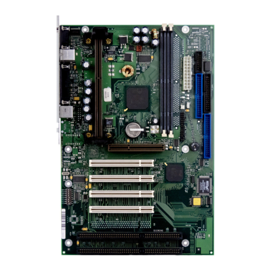
Page 12: Interfaces And Connectors
Features Interfaces and connectors Slot 1 1 = Serial port 1 4 = Parallel port 2 = PS/2 mouse port 5 = USB port 2 3 = PS/2 keyboard port 6 = USB port 1 4 - English A26361-D1156-Z120-6-7419... - Page 13 Features 4 5 6 Slot 1 1 = Serial chipcard reader interface or serial 5 = Wake On LAN port 2 6 = ON/OFF switch 2 = Power supply 7 = IDE drives 1 and 2 (primary) 3 = Floppy disk drive 8 = Connector for front panel 4 = IDE drives 3 and 4 (secondary) 9 = Fan 1 (e.
-
Page 14: Resource Table
Features Resource table assigned possible Possible Address Possible (hex) Keyboard IRQ1 Serial interface COM1 03F8, 02F8 03E8, 02E8 Serial port COM2 02E8, 02F8 03E8, 03F8 Floppy disk drive controller IRQ6 Parallel interface LPT1 5, 7 0278, 0378, 03BC 0, 1, 3 IRQ8 USB controller Mouse controller... -
Page 15: Settings With Switches
Settings with switches Settings with switches Slot 1 1 2 3 4 5 6 7 8 OPEN / OFF Switch 1 = must be set to off Switch 4 = reserved Switch 2 = System BIOS recovery (RCV) Switches 5 - 8 = clock frequency Switch 3 = Write protection for floppy disks English - 7 A26361-D1156-Z120-6-7419... -
Page 16: Recovering System Bios - Switch 2
Settings with switches Recovering System BIOS - switch 2 Switch RCV enables recovery of the old system BIOS after an attempt to update has failed. To restore the old system BIOS you need a Flash BIOS Diskette (please call our customer service center). - Page 17 Settings with switches Pentium II with 100 MHz Front Side Bus: processor switch 5 switch 6 switch 7 switch 8 350 MHz 400 MHz 450 MHz Pentium III with 100 MHz Front Side Bus: processor switch 5 switch 6 switch 7 switch 8 450 MHz 500 MHz...
-
Page 18: Add-On Modules
Add-on modules Add-on modules For all steps described in this chapter exit the suspend mode before switching off the device and then pull the power plug out of the power outlet! Even when you have run down the device, parts of the device (e. g. memory modules, AGP and PCI extension boards) are still energized. -
Page 19: Replacing The Processor
Add-on modules Replacing the processor Installing the processor If you wish to upgrade your system with a new processor, the processor bracket on the system board may need to be replaced beforehand. Should it be necessary to replace the bracket, please contact our customer service center. Depending on the design of the processor housing, the heat sink can be moved on the processor and the processor in the bracket. -
Page 20: Upgrading Main Memory
Add-on modules Upgrading main memory These slots are suitable for 16, 32, 64, 128 and 256 Mbyte SDRAM memory modules of the DIMM format. Memory modules with different memory capacities can be combined. You may only use unbuffered 3.3V memory modules. Buffered memory modules are not permitted. -
Page 21: Installing Network Board With Wol
Add-on modules Installing network board with WOL Ê Install the network board as described in the operating manual for your unit. Ê Push the WOL cable onto the WOL plug connector of the system board. To use the WOL functionality of a network board the power supply must provide a 5 V auxiliary voltage of at least 1 A. -
Page 22: Glossary
Glossary Glossary The technical terms and abbreviations given below represent only a selection of the full list of common technical terms and abbreviations. Not all technical terms and abbreviations listed here are valid for the described system board. ACPI ......Advanced Configuration and Power Interface AC'97 ......
Need help?
Do you have a question about the Siemens D1156 and is the answer not in the manual?
Questions and answers