Hirschmann MICE MS20 User Manual
Industrial ethernet switch mice
Hide thumbs
Also See for MICE MS20:
- Reference manual (572 pages) ,
- User manual (294 pages) ,
- Programming manual (116 pages)

Related Manuals for Hirschmann MICE MS20


Summary of Contents for Hirschmann MICE MS20
-
Page 1: User Manual
User Manual Installation Industrial ETHERNET Switch MICE MS20/MS30 MICE MS20 MICE MS30 MICE MS20/MS30 Technical support Release 2.0 02/06 HAC-Support@hirschmann.de... - Page 2 This publication has been created by Hirschmann Automation and Control GmbH according to the best of our knowledge. Hirschmann reserves the right to change the contents of this manual without prior notice. Hirschmann can give no guarantee in respect of the correctness or accuracy of the details in this publication.
-
Page 3: Table Of Contents
Safety instructions About this manual Legend Device description Description of the device variants 1.1.1 MS20-... /MS30-... combination options 1.1.2 Number of ports and media 1.1.3 Media modules 1.1.4 MB - 2T expansion module 1.1.5 SFP module Assembly and startup procedure Device installation 2.1.1 Unpacking and checking... -
Page 4: Safety Instructions
Hirschmann. The product can only be operated correctly and safely if it is transported, stored, installed and assembled properly and correctly. - Page 5 Housing Only technicians authorized by Hirschmann are permitted to open the housing. The lower covering panel of the MICE housing is grounded by the DIN rail and, as an option, by the separate ground screw. The switch basic module forms an inseparable unity. By removing the display and connecting parts, you risk the damage of the switch basic module.
-
Page 6: General Safety Instructions
Light Emit- ting Diode CLASS 2M, Wave length 650 nm, Power <2 mW, according to IEC/CEI 60825-1:2003-10. National and international safety regulations V Make sure that the electrical installation meets local or nationally ap- plicable safety regulations. MS20/MS30 Release 2.0 02/06... - Page 7 31/EEC and 93/68/EEC). In accordance with the above-named EU directives, the EU conformity declaration will be at the disposal of the relevant authorities at the follo- wing address: Hirschmann Automation and Control GmbH Stuttgarter Straße 45-51 D-72654 Neckartenzlingen Germany Phone ++49 7127 14 1480 The product can be used in living areas (living area, place of business, small business) and in industrial areas.
- Page 8 Recycling note: After usage, this product must be disposed of properly as electronic waste in accordance with the current disposal regulations of your county / state / country. MS20/MS30 Release 2.0 02/06...
-
Page 9: About This Manual
Switch. simultaneous configuration of several Switches. configure the relevant ports to be displayed red if there is no link state. Legend The commendations used in this manual have the following meanings: Listing Work step Subheading MS20/MS30 Release 2.0 02/06... -
Page 10: Device Description
Device description The MS20/MS30 devices consist of a switch with media modules that can be plugged into it. They allow you to construct switched industrial ETHERNET networks that conform to the IEEE 802. and 802.3u standards using copper wires or optical fibers in a bus or ring topology. You can connect terminal de- vices and other infrastructure components via twisted pair cables, multi- mode LWL and single-mode LWL. -
Page 11: Description Of The Device Variants
For the sake of simplicity, the basic switch module with various plugged in media modules will be referred to as MICE in this document. The MS20-... device variants are modular switches with up to 8, 16 or 24 * 10/100 Mbit Ethernet ports. You can choose the media for the ports via the media modules. - Page 12 Family Designed for MS20 Larger numbers of ports, number of 100 Mbit ports desired, temperature range, voltage range, certifi- cates and software variant can be selected MS30...
-
Page 13: Ms20
1.1.1 MS20-... /MS30-... combination options The product designation of your MS20/MS30 device is made from combining the desired product characteristics in accordance with the following table. The short designation is in column 3. Position Attribute Ident. Feature 1 to 4... -
Page 14: Number Of Ports And Media
Number of ports and media Device versions with 10/100 Mbit ports MS20-0800..., MS20-1600..., MS20-2400... Depending on the variant, the MS20 basic modules provide you with the following number of slots for media modules and the following maximum number of connectable network segments:... - Page 15 (power 1) terminal block (power 2) Fig. 2: Interfaces of the MS20-... and MS30-... on the bottom of the device Device versions with 1000 Mbit and 10/100 Mbit ports MS30-0802..., MS30-1602..., MS30-2402... Depending on the model, the MS30 basic modules offer you the...
-
Page 16: Media Modules
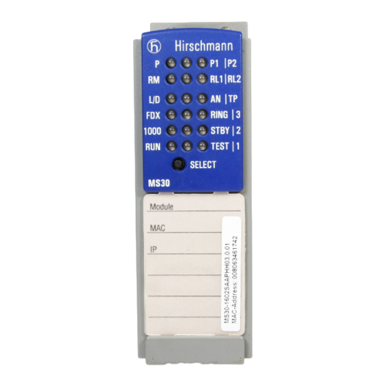
Fig. 3: Overview interfaces, display elements and controls of the MS30 The figure “Interfaces of the MS20-... and MS30-... on the bottom of the de- vice” on page 15 illustrates the interfaces on the bottom of the MS30 device. 1.1.3 Media modules The MICE media modules form the interface of the device to the LAN. - Page 17 – MM2 - 2FXS2 – – – – – 2, DSC – Table 2: Media connectors each MICE 2000 media module (number and kind) Port 1 Port 2 Port 3 Port 4 Fig. 4: Port assignment MS20/MS30 Release 2.0 02/06...
- Page 18 4, DSC – MM3-1FXL2/3TX1 – 3, RJ45 – – – – 1, DSC Table 3: Media connectors each MICE 3000 media module (number and kind) Port 1 Port 2 Port 3 Port 4 Fig. 5: Port assignment MS20/MS30 Release 2.0 02/06...
- Page 19 The 2-port media module MM4 - 2TX/SFP has two TP interfaces and two sockets for Hirschmann SFP modules. The 4-port media module MM4 - 4TX/SFP can also be used in the MS20/ MS30. It has four TP interfaces and four sockets for Hirschmann SFP mo- dules.
-
Page 20: Mb - 2T Expansion Module
1.1.4 MB - 2T expansion module The MB-2T expansion module allows you to add 2 slots to the MICE MS20-1600 / MS30-1602 basic modules for installing media modules. Fig. 7: MB - 2T expansion module 1.1.5 SFP module SFP modules are optical transceivers. SFP stands for Small Form-factor Pluggable and is often named mini-GBIC (GigaBit Interface Converter). -
Page 21: Assembly And Startup Procedure
V Tighten the 4 screws on the corners of the media module. V Fit the media modules one after the other from the left to the right. V Check whether the switch pre-setting suits your requirements. MS20/MS30 Release 2.0 02/06... -
Page 22: Filling Out And Attaching The Labels
- Name of the module - Port assignment of the module each port Fig. 9: Labels for basic module and media modules V Attach the labels included in the delivery to the basic module and the media modules as required. MS20/MS30 Release 2.0 02/06... -
Page 23: Assembling The Sfp Modules
1 are for con- module 2 are for connecting the HIPER- necting the HIPER-Ring) Ring. MS20: In the ON position, port 1 from modules 1 and 2 are for connecting the HIPER-Ring. Stand-by With the redundant coupling of rings, you... -
Page 24: Adjusting The Dip Switch Settings On The Mice Mm3-2Aui Media Module (If Existent)
2 Ring port 3 Stand-by 4 Configuration Fig. 11: 4-pin DIP switch on the MICE MS20-.../MS30-... basic module V Check whether the switch default settings match your requirements before starting the device. 2.1.6 Adjusting the DIP switch settings on the... -
Page 25: Terminal Block For Supply Voltage And Signal Contact
The following conditions are reported in stand-by mode Control cable disrupted Control cable shorted Partner device is in stand-by mode The following conditions are reported in normal mode: Control cable shorted Partner device is in normal mode MS20/MS30 Release 2.0 02/06... -
Page 26: Connecting The Terminal Blocks, Startup Procedure
2.1.8 Connecting the terminal blocks, startup procedure V Pull the terminal blocks off the device and connect the power supply and signal lines. MICE MS20/30 switch basic module with 18 to 60 VDC voltage range MICE MS20/30 switch basic module... -
Page 27: 10Connecting The Data Lines
The grounding of the lower panel of the housing of the device is effected with the hat rail and, optionally, with the separate ground screw (see Fig. “Overview interfaces, display elements and controls of the MS20 -...” on page 14). - Page 28 The pin assignment corresponds to MDI-X. BI_DC- Pin 8 BI_DC+ Pin 7 BI_DA- Pin 6 BI_DD- Pin 5 Pin 4 BI_DD+ BI_DA+ Pin 3 BI_DB- Pin 2 BI_DB+ Pin 1 Fig. 16: Pin assignment of a 1000 MBit/s twisted pair interface MS20/MS30 Release 2.0 02/06...
-
Page 29: Aui Connection
Connect the ports of the media modules plugged into the basic module as required in order to set up your industrial ETHERNET or expand your existing network. V Connect the data lines according to your requirements. MS20/MS30 Release 2.0 02/06... -
Page 30: 11Assembling The Mb - 2T Expansion Module
2.1.11 Assembling the MB - 2T expansion module The expansion module MB-2T allows you to add 2 slots to the MS20-1600 and MS30-1602 basic modules for installing media modules. The MB-2T expansion module can be installed while in running operation. -
Page 31: Device Status
The signal contact 1 is open, i.e. it indicates an error lit yellow The signal contact 1 is open, the “manual setting” is active not lit The signal contact 1 is closed, i.e. it does not indicate an error MS20/MS30 Release 2.0 02/06... - Page 32 The LEDs P1/P2 light green. The status LED “RM” blinks green/yellow. The status LEDs “RELAY1/RELAY2” blinks yellow/red. The display status LEDs blink green. The port status LEDs of the media modules blink green/ yellow. MS20/MS30 Release 2.0 02/06...
- Page 33 Stand-by partner existing TP/FO – Twisted pair / fiber Meaning optic (green/yellow LED) lit green The port LEDs of the media modules display twisted pair ports lit yellow The port LEDs of the media modules display F/O ports MS20/MS30 Release 2.0 02/06...
-
Page 34: Carrying Out Basic Settings
The USB socket offers an interface for the local connection of an Auto- Configuration Adapter ACA 21-USB. It is a device for saving/loading the configuration and for loading the software. Pin number Signal name - Data + Data Ground MS20/MS30 Release 2.0 02/06... - Page 35 Pin 1 n.c. Fig. 19: Pin assignment of the V24 interface Note: In chapter “Technical data” on page 37 ff you find the order number for the terminal access cable which is to be ordered separately. MS20/MS30 Release 2.0 02/06...
-
Page 36: Disassembling
Fig. 20: Disassembling the device Disassembling the SFP modules V Pull the SFP module on the opened lock out off the socket. V Close the socket with the protective cap. Fig. 21: Disassembling the SFP module MS20/MS30 Release 2.0 02/06... -
Page 37: Technical Data
Class 1 conforming to EN 60825-1 (2001) Protection types IP 20 At 48 VDC power supply (voltage range C (18...60 VDC), see table “Combination options of the MS20/MS30 device versions” on page EMV and stability EMV interference proof EN 61000-4-2... - Page 38 IEC 870-2-2 Table 3 Normal Installation in line with EN61850-3 Product code A: Certification = CE, UL Product code B: Certification = CE, UL, GL, Railway, Sub Station, see “Combination options of the MS20/MS30 device versions” on page 13 Network size AUI port Length of a AUI cable...
- Page 39 F/O adapter in line with IEEE 802.3-2002 clause 38 (single-mode fiber offset-launch mode conditioning patch cord) Power consumption/power output , temperature range and order numbers Order numbers of the MICE basic modules see table “Combination options of the MS20/MS30 device versions” on page 13. Operating Power Power output Operating Basic module temperature,...
- Page 40 0 Btu (IT)/h 0 °C to +60 °C 943 733-002 Interfaces MICE MS20-..., MS30-... V.24 Port: external management, AutoConfiguration Adapter ACA 11 2 terminal blocks: 1 x indicator contact each, 1 A maximum, 24 V 1 x voltage supply each...
-
Page 41: Scope Of Delivery
MICE 3000 media modules page 18 MICE 4000 media modules page 19 Scope of delivery Device Scope of delivery MICE MS20-.../MS30-... device MS20-.../MS30-... 2 terminal blocks for supply voltage and indicator contact CD-ROM with manual ML-MS2/MM lables description and operating instructions Accessories Name... - Page 42 The following table shows the status of the certifications of the MICE product family. Standard MS20/MS30 cUL 508 / CSA C22.2 No.142 pending cUL 1604 / CSA C22.2 No.213 pending Germanischer Lloyd pending Table 13: Certifications, actual state see www.hirschmann.com * without MM3 - 2AUI MS20/MS30 Release 2.0 02/06...
-
Page 43: Further Support
Further support Technical questions and training courses In the event of technical queries, please talk to the Hirschmann contract partner responsible for looking after your account or directly to the Hirschmann office. You can find the addresses of our contract partners on the Internet: http://www.hirschmann.com... - Page 44 !'#!
Need help?
Do you have a question about the MICE MS20 and is the answer not in the manual?
Questions and answers