
Related Manuals for KOBE IN2636SQB


Summary of Contents for KOBE IN2636SQB
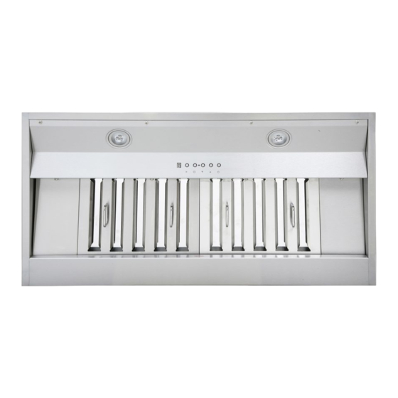
- Page 1 KOBE Brand Range Hood Model No.: IN2636SQB IN-026 SERIES INSTALLATION INSTRUCTIONS AND OPERATION MANUAL...
-
Page 2: Table Of Contents
- READ AND SAVE THESE INSTRUCTIONS - CONTENTS IMPORTANT SAFETY INSTRUCTIONS ................ 1 COMPONENTS OF PACKAGE ..................3 INSTALLATION ....................... 4 OPERATING INSTRUCTIONS ..................8 MAINTENANCE ......................11 SPECIFICATIONS ......................12 MEASUREMENTS & DIAGRAMS................. 13 PARTS LIST ........................15 CIRCUIT DIAGRAM ...................... 17 TROUBLE SHOOTING .................... -
Page 3: Important Safety Instructions
KOBE RANGE HOODS authorized agents will automatically void the warranty. KOBE RANGE HOODS will not be held responsible for any damages to personal property or real estate or any bodily injuries whether caused directly or indirectly by the range hood. - Page 4 What to Do In The Event Of a Range Top Grease Fire • SMOTHER FLAMES with a tight fitting lid, cookie sheet, or metal tray, and then turn off the burner. KEEP FLAMMABLE OR COMBUSTIBLE MATERIAL AWAY FROM FLAMES. If the flames do not go out immediately, EVACUATE THE AREA AND CALL THE FIRE DEPARTMENT or 911.
-
Page 5: Components Of Package
{I} Rear Section of Liner {D} Baffle Filter – 2 {E} Oil Tunnel – 1 {F} Handle & Screws Package – 1 {G} Wireless Control – 1 FOR MORE INFORMATION, PLEASE VISIT OUR WEBSITE WWW.KOBERangeHoods.com CONT ACT KOBE RANGE HOODS AT 1-877-BUY-KOBE (1-877-289-5623) -
Page 6: Installation
INSTALLATION PLEASE READ ENTIRE INSTRUCTIONS BEFORE PROCEEDING Calculation before Installation To calculate installation, please refer to TABLE 1. (All calculation in inches.) - FOR UNDER THE CABINET - TABLE 1 A = Height of Floor to Ceiling B = Height of Floor to Counter Top (Standard: 36") C = Height of Counter Top to Wood Frame Bottom (Recommended 27"... - Page 7 For Insert Installation - Figure 1 Preparation Before Installation NOTE: TO AVOID DAMAGE TO YOUR HOOD, PREVENT DEBRIS FROM ENTERING THE VENT OPENING. Decide the location of the venting pipe from the hood to • the outside. Refer to Figure 1. A straight, short vent run will allow the hood to perform •...
- Page 8 the back edge of the custom wood frame. Use a pen to Figure 5 trace the outline of the pre-cut area. Remove the liner and proceed to Hood Preparation Before Installation. 9. Install the rear section of the liner with 6 screws (not included).
- Page 9 before installing the insert. 20. Determine the proper location for the Power Supply Figure 9 Cable. Make a wiring access hole using a drill bit. Install the wire cable and seal the gap around hole. 21. Cut out the opening where the insert will be installed. (Figure 5) Hood Installation NOTE: USE HAND TOOLS ONLY.
-
Page 10: Operating Instructions
OPERATING INSTRUCTIONS This KOBE hood is equipped with five electronic push buttons with LED array, six electronic button wireless control, twin vertical centrifugal squirrel cage fan with stainless steel baffle filter, ISC (Integrated Sensor Control), two bright 120-volt 40-watt socket (light bulbs not included), and one oil tunnel. - Page 11 99 mins. To clear the timer, press Timer Control twice. Baffle Change Indicator The display will indicate when baffle filter needs cleaning. Remove to clean the baffle filter. (To purchase replacement filters, please contact your local KOBE dealer or call 626-350-1355)
- Page 12 (Each press of Light Control will cycle the light intensity through high, low, and off.) Speed Control Press the Speed control to activate the Fan. The KOBE hood will start on High speed. Each press of the Speed Control button will cycle through the various speeds.
-
Page 13: Maintenance
MAINTENANCE SAFETY WARNING NEVER PUT YOUR HAND INTO AREA HOUSING THE FAN WHILE THE FAN IS OPERATING. Cleaning Hood Surface CAUTION NEVER USE ABRASIVE CLEANERS, PADS, OR CLOTHS. DO NOT USE PAPER TOWEL ON STAINLESS STEEL. For optimal operation, clean range hood and all baffle/spacer/filter/oil tunnel/oil container regularly. *** Regular care will help preserve the appearance of the hood. -
Page 14: Specifications
SPECIFICATIONS MODEL / SIZE IN2636SQB COLOR 20-Gauge Commercial Stainless Steel CONSUMPTION / AMPERE 290W / 2.5A VOLTAGE 120V 60Hz NUMBER OF MOTORS FAN TYPE: CENTRIFUGAL Twin Vertical Squirrel Cage EXHAUST Top 7” Round with Damper CONTROLS 5 Push-Button with LED Array... -
Page 15: Measurements & Diagrams
MEASUREMENTS & DIAGRAMS All ( ) are in millimeter. All inch measurements are converted from millimeters. Inch measurements are estimated. MODEL NO: IN2636SQB Side View Bottom View Back View Front View... - Page 16 Stainless Steel Liner (Sold Separately) Model No. INL36252A Model No. INL42252A Model No. INL48252A...
-
Page 17: Parts List
PARTS LIST MODEL NO: IN2636SQB DESCRIPTION MODEL/SIZE PART NO. Hood Casing IN2636-02-01 Oil Tunnel IN2636-03-04 Wiring Box IN2636-06-01 IN2636-08-01 Baffle Filter Support IN2636-03-07 Bracket Hood Casing Support IN2636-02-08 Indicator Sensor IN2636-05-01 Baffle Filter Support IN2636-03-05 Baffle Filters IN2636-03-01 Baffle Filter Handles... - Page 18 Optional Liner (Sold Separately)
-
Page 19: Circuit Diagram
CIRCUIT DIAGRAM MODEL NO.: IN2636SQB... -
Page 20: Trouble Shooting
TROUBLE SHOOTING Issue Possible Cause Solution After Installation, The power is not on. Make sure the circuit breaker and the unit’s power is both motors and ON. Use a voltage meter to check the power supply. lights are not The wire connection is not secure. Check and tighten wire connection. -
Page 21: Disclaimer
2. PLEASE INSPECT CONTENTS OF PACKAGE(S) CAREFULLY UPON RECEIVING! We must be notified in writing of any damages and/or missing parts within the allocated days upon your receipt of package(s). Contact your local KOBE dealer or distributor or call KOBE for the time limit. -
Page 22: Warranty
WARRANTY WARRANTY CERTIFICATE KOBE Range Hoods, Inc. warrants all products manufactured or supplied by it to be free from defects in workmanship and materials. Its obligations pursuant to this warranty are limited to a period of two years from the date of purchase and to the repair or replacement at its option and subject to the terms and conditions stated below, of any component part, which its examination shall disclose to be so defective. - Page 23 Some states do not allow limitations on the duration of implied warranties. This warranty gives you specific legal rights, and may also have rights, which vary from state to state. SERVICE For service contact: KOBE Range Hoods 11775 Clark St. Arcadia, CA 91006, U.S.A Tel:1-877-BUY-KOBE (1-877-289-5623) Email: customer.service@KOBERangeHoods.com...
-
Page 24: Product Registration
KOBE Range Hoods Agent or KOBE Range Hoods as applicable. Keep proof of purchase (original invoice) handy for inspection. - Page 25 CA 91006, U.S.A http://www.KOBERangeHoods.com This KOBE hood is made for use in the USA and CANADA only. We do not recommend using this hood overseas as the power supply may not be compatible and may violate the electrical code of that country. Using a KOBE hood overseas is at your own risk and will void your warranty.
- Page 27 ® KOBE Hotte de ventilation KOBE de modèle : IN2636SQB SÉRIE IN-026 NOTICE D'INSTALLATION ET MODE D’EMPLOI...
- Page 28 - LIRE ET CONSERVER CES INSTRUCTIONS - CONSIGNES DE SÉCURITÉ IMPORTANTES ..............27 CONTENU DE L’EMBALLAGE ....................29 INSTALLATION ........................30 MODE D’EMPLOI........................35 ENTRETIEN PRÉVENTIF ...................... 39 SPECIFICATIONS ......................... 40 MESURES ET SCHÉMAS ..................... 41 LISTE DES PIÈCES ....................... 43 SCHÉMA DE CÂBLAGE ......................
-
Page 29: Consignes De Sécurité Importantes
NOTE- La garantie de cet appareil sera nulle sans le reçu d'un distributeur autorisé de KOBE RANGE HOODS ou si l'appareil est endommagé par une utilisation inadéquate, une installation déficiente, un usage inapproprié, un mauvais traitement, de la négligence ou... - Page 30 Que faire en cas d'un incendie de graisse sur la cuisinière? ÉTOUFFER LES FLAMMES à l'aide d'un couvercle hermétique, une plaque à biscuits ou un • plateau en métal, puis fermer le rond ou le brûleur. GARDER LES MATÉRIAUX INFLAMMABLES OU COMBUSTIBLES LOIN DES FLAMMES. Si les flammes ne s'éteignent pas immédiatement, ÉVACUER LA ZONE ET APPELER LE SERVICE D'INCENDIE ou le 911.
-
Page 31: Contenu De L'emballage
{E} Récipient à graisse – 1 {F} Ensemble de poignées et de vis – 1 {G} Commande sans fil – 1 ♦ POUR DE PLUS AMPLES RENSEIGNEMENTS, VEUILLEZ VISITER NOTRE SITE WEB WWW.KOBERANGEHOODS.COM OU COMMUNIQUER AVEC KOBE RANGE HOODS AU 1-877-BUY-KOBE (1-877-289-5623) -
Page 32: Installation
INSTALLATION VEUILLEZ LIRE LES INSTRUCTIONS AU COMPLET AVANT L’INSTALLATION Prise de mesures avant l’installation Pour calculer les mesures, veuillez vous référer au TABLEAU 1. (Toutes les mesures sont données en pouces). HOTTE INSTALLÉE SOUS UNE ARMOIRE – TABLEAU 1 A = Hauteur entre le plancher et le plafond B = Hauteur entre le plancher et le plan de travail C = Hauteur désirée entre le plan de travail et le dessous de la hotte (dégagement recommandé... - Page 33 – Installation de l’insert – Figure 1 Préparation avant l’installation NOTE : AFIN DE PRÉVENIR TOUT DOMMAGE À LA HOTTE, IL FAUT EMPÊCHER LES DÉBRIS DE PÉNÉTRER DANS L'OUVERTURE VENTILATION. Choisir l’emplacement du conduit de ventilation de la • hotte à l’extérieur. Voir la Figure 1. Un conduit court et droit permet de maximiser le •...
- Page 34 Figure 4 Installation du revêtement 5. La base du cadre en bois sur mesure doit être robuste afin de tenir compte du découpage pour l’insert. La base doit être encastrée tout en considérant la hauteur du revêtement (Voir les dimensions du revêtement à la page 42).
- Page 35 15. Ranger les fils dans le boîtier de câblage. Note : Raccorder tous les fils électriques avant d’installer Figure 8 l’insert. NE PAS alimenter avant que l’installation soit terminée. Installation du système de conduits 16. Utiliser un tuyau d'acier de 7 po (tout en respectant les codes du bâtiment de votre secteur) pour raccorder les conduits de la hotte au réseau de gaines au-dessus.
- Page 36 25. Installer l’insert au moyen de trous de fixation arrière et Figure 10 avant qui sont situés à 1-1/2 po (38 mm) au-dessus de la base de l’insert (les vis ne sont pas comprises). 26. Pour une installation plus sécuritaire, utiliser les trous de fixation situés sur les côtés de l’insert.
-
Page 37: Mode D'emploi
MODE D’EMPLOI Cette hotte de cuisinière KOBE est munie d’un tableau à cinq boutons-poussoirs électroniques à DEL, six boutons à commandes électroniques sans fil, un ventilateur double à aubes inclinées vertical avec filtre déflecteur en acier inoxydable, une « commande de capteur intégré » (Integrated Sensor Control - ICS), deux lampes à... - Page 38 Commande Marche/Arrêt Appuyer sur la commande Marche/Arrêt (« ON/OFF ») pour allumer ou éteindre la hotte. L’élément affiché : Commande de vitesse (Chaque fois que la commande de vitesse est enfoncée, le cycle passe à la vitesse ™ suivante : élevée, à moyenne, à basse et à QuietMode L’élément affiché...
- Page 39 élevée, à basse et à éteinte). Commande de vitesse Appuyer sur le bouton de la commande de vitesse pour activer le ventilateur. La hotte KOBE démarre à vitesse élevée. Chaque fois que le bouton de commande de vitesse est enfoncé,...
- Page 40 ™ Appuyer sur ▼ pour le cycle de vitesse élevée, à moyenne, à basse et à QuietMode ™ Appuyer sur ▲ pour le cycle de vitesse élevée, à QuietMode , à basse et à moyenne. Commande de minuterie Appuyer sur le bouton de commande de minuterie pour activer le mode Minuterie.
-
Page 41: Entretien Préventif
ENTRETIEN PRÉVENTIF CONSIGNE DE SÉCURITÉ NE JAMAIS METTRE LES MAINS DANS L’AIRE ABRITANT LE VENTILATEUR ALORS QUE CELUI-CI EST EN FONCTION. Nettoyage des surfaces de la hotte AVERTISSEMENT NE JAMAIS EMPLOYER DE NETTOYANTS ABRASSIFS, DE LAINES D’ACIER OU DE TISSUS ABRASIFS. NE JAMAIS UTILISER D’ESSUIE-TOUT SUR UNE SURFACE EN ACIER INOXYDABLE Pour favoriser un rendement optimal, nettoyer régulièrement les surfaces de la hotte de ventilation et tout réflecteur/entretoise/filtre/récupérateur de graisse/récipient à... -
Page 42: Specifications
SPECIFICATIONS MODÈLE / FORMAT IN2636SQB COULEUR feuille en acier inoxydable commercial d’épaisseur CONSOMMATION / AMPÈRE 290 W / 2.5 A VOLTAGE 120 V - 60 Hz NOMBRE DE MOTEURS TYPE DE VENTILATEUR : CENTRIFUGE Ventilateur à aubes inclinées verticales ÉVACUATION évent rond de 7 po avec clapet... -
Page 43: Mesures Et Schémas
MESURES ET SCHÉMAS ♦ Toutes les mesures entre parenthèses sont en millimètres. ♦ Toutes les mesures en pouces sont converties à partir de millimètres. Les mesures sont estimées. DE MODÈLE : IN2636SQB Vue de côté Vue de dessous Vue arrière... - Page 44 NOTE DE LA TRADUCTRICE : SVP REMPLACER LES GUILLEMETS PAR po ex.: 1-1/8" = 1 1/8 po Revêtement en acier inoxydable (vendu séparément) de modèle : INL36252A INL42252A INL48252A NOTE DE LA TRADUCTRICE : SVP REMPLACER LES GUILLEMETS PAR po ex.: 1-1/8" = 1 1/8 po...
-
Page 45: Liste Des Pièces
LISTE DES PIÈCES DE MODÈLE : IN2636SQB DESCRIPTION MODÈLE/FORMAT DE PIÈCE Caisson de la hotte IN2636-02-01 Récupérateur de graisse IN2636-03-04 Boîtier de câblage IN2636-06-01 ISC – (Integrated Sensor Control) IN2636-08-01 Commande de capteur intégré IN2636-03-07 Support du caisson de la hotte... - Page 46 Revêtement optionnel (vendu séparément)
-
Page 47: Schéma De Câblage
SCHÉMA DE CÂBLAGE DE MODÈLE : IN2636SQB CARTE PROCESSEUR - ROUGE CAPACITOR - CONDENSATEUR BLACK - NOIR MOTOR - MOTEUR BLUE - BLEU BLACK - NOIR ORANGE - ORANGE WHITE - BLANC GREEN - VERT GREEN -VERT BROWN - BRUN... -
Page 48: Trouble Shooting
TROUBLE SHOOTING Problème Cause probable Solution Après Pas d’alimentation électrique. Assurez- Utilisez un voltmètre pour vérifier l’alimentation en l’installation, vous que le disjoncteur et que électricité. les deux l’alimentation électrique moteurs et soient en marche. les lumières ne Le câblage n’est pas bien installé. Vérifiez et serrez les connexions de fils. -
Page 49: Avis De Non-Responsabilité
à l'intérieur du délai alloué à partir de la réception de la marchandise. Communiquer avec votre représentant ou distributeur local de KOBE ou appeler chez KOBE pour connaître le délai alloué. LES RÉCLAMATIONS QUI NOUS PARVIENDRONT APRÈS LE DÉLAI ALLOUÉ SERONT REFUSÉES. -
Page 50: Garantie
(ou, à notre discrétion, l'appareil pourra être remplacé), sans frais, par un agent autorisé de KOBE Range Hoods, Inc. ou par KOBE Range Hoods, Inc. selon le cas. Conservez votre preuve d'achat (ou facture d'origine) pour inspection. - Page 51 à l'extérieur du territoire de ventes principal du détaillant ou du territoire de service de l'agent autorisé de KOBE Range Hoods le plus près, selon le cas, de tous les frais de déplacement et de tous les frais de transport de la hotte ou de pièces de celle-ci jusqu'au détaillant ou au technicien de service (aller-retour).
-
Page 52: Enregistrement Du Produit
à notre discrétion, l'appareil pourra être remplacé, sans frais, par un agent autorisé de KOBE Range Hoods, Inc. ou par KOBE Range Hoods, Inc. selon le cas. Conservez votre preuve d'achat (ou facture d'origine) pour inspection. - Page 53 Il n’est pas recommandé d’utiliser cette hotte à l’étranger puisque l’alimentation électrique pourrait ne pas être compatible et enfreindre le code de l’électricité de ce pays. L’usage de la hotte KOBE à l’étranger est à votre propre risque et la garantie sera annulée.
- Page 55 Campana de Extracción KOBE Modelo No.: IN2636SQB SERIE IN-026 INSTRUCCIONES DE INSTALACIÓN Y MANUAL DE OPERACIÓN...
- Page 56 - LEA Y CONSERVE ESTAS INSTRUCCIONES - ÍNDICE INSTRUCCIONES IMPORTANTES DE SEGURIDAD............55 COMPONENTES DEL PAQUETE ..................57 INSTALACIÓN ........................58 INSTRUCCIONES DE OPERACIÓN ..................63 MANTENIMIENTO ......................... 66 ESPECIFICACIONES ......................67 MEDIDAS Y DIAGRAMAS ..................... 68 LISTADO DE PIEZAS ......................70 DIAGRAMA DE CIRCUITO ....................
-
Page 57: Instrucciones Importantes De Seguridad
KOBE RANGE HOODS anulará la garantía automáticamente. KOBE RANGE HOODS no se hará responsable por cualquier daño a la propiedad personal o inmobiliario ni por las lesiones físicas que se hayan causado ya sea directa o indirectamente por la campana de extracción. - Page 58 Qué Hacer en Caso de un Incendio Causado por la Grasa Acumulada en las Hornillas de la Estufa • SOFOQUE LAS LLAMAS con una tapadera, una bandeja para hornear galletas o una bandeja de metal que quede bien ajustada y luego apague la hornilla. MANTENGA TODO EL MATERIAL INFLAMABLE O COMBUSTIBLE LEJOS DE LAS LLAMAS.
-
Page 59: Componentes Del Paquete
{E} Conducto para Aceite - 1 {I} Sujetador y Paquete de Tornillos - 1 {G} Control Inalámbrico - 1 PARA OBTENER MÁS INFORMACIÓN, POR FAVOR VISITE NUESTRO SITIO DE INTERNET WWW.KOBERangeHoods.COM O CONT ACTE A KOBE RANGE HOODS AL 1-877-BUY-KOBE (1-877-289-5623) -
Page 60: Instalación
INSTALACIÓN POR FAVOR, LEA LAS INSTRUCCIONES COMPLETAMENTE ANTES DE CONTINUAR Cálculo antes de la Instalación Para realizar el cálculo para la instalación, por favor consulte la TABLA 1. (Todos los cálculos están hechos en pulgadas). -PARA INSTALACIÓN DEBAJO DE UN GABINETE- TABLA 1 A = Altura del Piso al Techo B = Altura del Piso a la Superficie del Mostrador... - Page 61 - Para la Instalación del Inserto - Figura 1 Preparación Antes de la Instalación NOTA: PARA EVITAR CAUSAR DAÑOS A SU CAMPANA, Tubo Redondo EVITE QUE DESECHOS PENETREN EN LA RENDIJA DE de 7” Tapa del VENTILACIÓN Techo Decida la ubicación para colocar el conducto de •...
- Page 62 Figure 4 Instalación de la Cubierta El marco de madera personalizado deberá tener una base sólida para poder colocar el recorte del inserto. La base deberá estar empotrada para acomodar la altura de la cubierta (Ver las dimensiones de la cubierta en la Página 69).
- Page 63 15. Guarde los cables en la caja del cableado. Figure 8 Nota: Conecte todos los cables eléctricos antes de instalar el inserto. NO encienda la corriente hasta que haya terminado con la instalación. Instalación de la Red de Conductos Utilice un tubo de acero de 7" (según las leyes de construcción en su área) para conectar los ductos de la campana con la red de conductos arriba.
- Page 64 posteriores y delanteros ubicados a 1-1/2” (38mm) Figure 10 desde la base del inserto (tornillos no incluidos). Para lograr una instalación más segura, utilice los agujeros de montaje ubicados en el lado del inserto. 27. Asegúrese que el inserto esté bien sujeto antes de soltarlo.
-
Page 65: Instrucciones De Operación
INSTRUCCIONES DE OPERACIÓN Esta campana de extracción KOBE viene equipada con cinco botones electrónicos con un sistema de LEDs, un control inalámbrico de seis botones, un ventilador de jaula de ardilla centrífuga doble con un filtro deflector de acero inoxidable, control de sensor integrado (ISC), dos receptáculos para foco brillante de 120v 40W (focos no incluidos) y un conducto para aceite. - Page 66 Remueva el filtro deflector para limpiarlo. (Para comprar filtros de repuesto, por favor contacte a su agente KOBE local o llame al 626- 350-1355) Los seis botones de control para el control remoto inalámbrico son: Control Encendido/Apagado, Control...
- Page 67 (Cada vez que oprima el Control de Luz se cambiará la intensidad de las luces entre alto, medio y apagado.) Control de Velocidad Oprima el Control de Velocidad para activar el Ventilador. La campana KOBE iniciará en velocidad Alta. Cada vez que oprima el botón de Control de Velocidad se cambiarán las diferentes velocidades.
-
Page 68: Mantenimiento
MANTENIMIENTO ADVERTENCIA DE SEGURIDAD NUNCA COLOQUE SUS MANOS DENTRO DE LA CAJA DEL VENTILADOR MIENTRAS ÉSTE SE ENCUENTRE FUNCIONADO. Limpieza de la Superficie de la Campana PRECAUCIÓN: NUNCA UTILICE LIMPIADORES, ALMOHADILLAS PAÑOS ABRASIVOS. NO UTILICE TOALLAS DE PAPEL SOBRE EL ACERO INOXIDABLE. -
Page 69: Especificaciones
ESPECIFICACIONES MODELO / TAMAÑO IN2636SQB COLOR Acero Inoxidable de Clasificación Comercial Calibre 20 CONSUMO / AMPERIOS 290W / 2.5A VOLTAJE 120V 60Hz NUMERO DE MOTORES TIPO DE VENTILADOR: CENTRIFUGO Jaula de Ardilla Vertical Doble EXTRACTOR Circular Superior de 7” con Regulador... -
Page 70: Medidas Y Diagramas
MEDIDAS Y DIAGRAM AS Todas las medidas ( ) están en milímetros. Todas las medidas en pulgadas han sido convertidas de milímetros. Las medidas en pulgadas son medidas aproximadas. MODELO NO: IN2636SQB Vista Lateral Vista Inferior Vista Posterior Vista de Frente... - Page 71 Cubierta de Acero Inoxidable (Vendida por Separado) Modelo No. INL36252A Modelo No. INL42252A Modelo No. INL48252A...
-
Page 72: Listado De Piezas
LISTADO DE PIEZAS MODELO NO: IN2636SQB DESCRIPCIÓN MODELO / TAMAÑO PIEZA NO. Carcasa de la Campana IN2636-02-01 Conducto de Aceite IN2636-03-04 Caja de Cableado Eléctrico IN2636-06-01 Control del Sensor Integrado (ISC) IN2636-08-01 Herraje de Soporte del Filtro Deflector IN2636-03-07 Soporte de la Carcasa de la Campana... - Page 73 Cubierta Opcional (Vendida por Separado)
-
Page 74: Diagrama De Circuito
DIAGRAMA DE CIRCUITO MODELO NO.: IN2636SQB PLACA DE CONTROL SENSOR INDICA- PLACA DE PROCESADOR LÁMPARA DE HALÓGENO CONDENSADOR CONDENSADOR 12uF/250V 12uF/250V BLACK = NEGRO RED = ROJO GRAY = GRIS GREEN = VERDE BROWN = CAFÉ WHITE = BLANCO... -
Page 75: Instrucciones Importantes De Seguridad
INSTRUCCIONES IMPORTANTES DE SEGURIDAD Problema Posible Causa Solución Después de la No está encendido. Asegúrese que el interruptor de circuitos y la Instalación, unidad se encuentren encendidos. Utilice un ninguno de los medidor de voltaje para verificar la energía de motores ni las entrada. -
Page 76: Cláusula De Exención
Se nos deberá notificar por escrito sobre cualquier daño y/o piezas faltantes dentro del periodo de días establecidos luego de haber recibido su paquete(s). Contacte a su distribuidor o concesionario KOBE o llame a KOBE para obtener información sobre el límite de tiempo. RECLAMOS SERÁN... -
Page 77: Garantía
(o reemplazada a nuestra discreción) sin costo alguno por parte de un Agente autorizado de KOBE Range Hoods o KOBE Range Hoods según corresponda. Tenga a la mano un comprobante de compra (o la factura original) para su verificación. - Page 78 Agente autorizado de KOBE Range Hoods más cercano según corresponda, así como de cualquier gasto de viaje y cualquier costo de transporte de la campana de extracción y piezas desde y hacia el concesionario y Agente de Servicio.
-
Page 79: Registro Del Producto
Agente autorizado de KOBE Range Hoods o KOBE Range Hoods según corresponda. Tenga a la mano un comprobante de compra (factura original) para su verificación. - Page 80 Utilizar una campana KOBE en el extranjero será a su propio riesgo y anulará la garantía.
Need help?
Do you have a question about the IN2636SQB and is the answer not in the manual?
Questions and answers