Sign In
Upload
Manuals
Brands
SEA TEL Manuals
Antenna
9707D-70 C-BAND TX
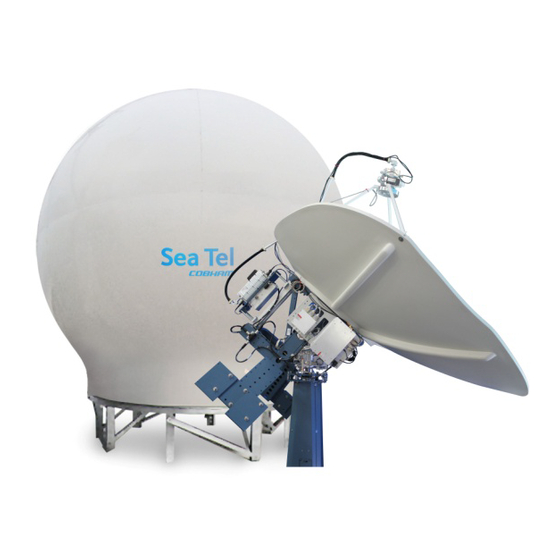
SEA TEL 9707D-70 C-BAND TX Manuals
Manuals and User Guides for SEA TEL 9707D-70 C-BAND TX. We have
1
SEA TEL 9707D-70 C-BAND TX manual available for free PDF download: Installation And Operation Manual
SEA TEL 9707D-70 C-BAND TX Installation And Operation Manual (83 pages)
C-BAND TX/RX ANTENNA
Brand:
SEA TEL
| Category:
Antenna
| Size: 2 MB
Table of Contents
Table of Contents
5
1 Introduction
9
General System Description
9
Purpose
9
System Components
9
General Scope of this Manual
10
Quick Overview of Contents
10
2 Operation
11
System Power-Up
11
Antenna Initialization
11
Antenna Stabilization
11
Stabilized Pedestal Assembly Operation
12
Tracking Operation
12
Antenna Polarization Operation
12
Low Noise Block Converter Operation
12
Rf Equipment
12
Radome Assembly Operation
12
3 Basic System Information
13
Satellite Basics
13
C-Band Receive Frequency (3.7-4.2Ghz)
13
Blockage
13
Rain Fade
13
Signal Level
13
Satellite Footprints
14
Satellite Circular Polarization
14
Antenna Basics
14
Unlimited Azimuth
14
Elevation
14
Antenna Polarization
14
Stabilization
14
Search Pattern
14
Tracking Receiver - Single Channel Per Carrier Receiver
15
Tracking
15
Components of the System Configuration
16
Antenna ADE Assembly
17
Antenna Control Unit
17
Above Decks AC Power Supply
17
Positive Satellite ID
18
Open Antenna-Modem Interface Protocol (Openamip™) Specification
18
Overview
18
Interface Requirements
18
Utilized Openamip Commands
19
4 Installation
21
General Cautions & Warnings
21
Site Survey
22
Preparing for the Installation
22
Unpack Shipping Crates
22
Inspect / Inventory
22
Prepare ADE Mounting Location
22
Preparing BDE Location
23
Installing the System Cables
23
Assembling the Ade
23
144" Radome, Baseframe and Antenna Pedestal System Assembly
23
Preparing the ADE for Lift
24
Installing the Ade
24
4.5.1. Hoist
24
Install Antenna/Radome/Baseframe
25
Cooling Unit Assembly - TX SYSTEMS ONLY
25
Install Bde Equipment
25
Acu & Tms
25
Other BDE Equipment
25
Cable Terminations
25
At the Radome
25
Final Assembly
25
Mount RF Equipment (TXRX Only)
25
Remove Stow Braces/Restraints
26
Verify All Assembly and Wiring Connections
26
Balance Antenna Pedestal
26
Power-Up the ADE
26
Initialization
26
Home Flag Position
26
Bde
26
4.10. Setup
26
5 Setup
27
Operator Settings
27
Optimizing Targeting (Auto Trim)
27
Optimizing Targeting (Manually)
27
Optimizing Auto-Polarization TX/RX
27
Calibrating Relative Antenna Position (Home Flag Offset)
28
To Calculate HFO
28
To Enter the HFO Value
30
Radiation Hazard and Blockage Mapping (AZ LIMIT Parameters)
30
Tx Polarity Setup
30
Sat Skew Setting
31
Polarity Angle (Polang) Parameters
31
Default Setup Parameters
32
6 Functional Testing
33
Acu / Antenna System Check
33
Check
33
Latitude/Longitude Auto-Update Check
33
Azimuth & Elevation Drive
33
Four Quadrant Tracking Test
33
7 Maintenance and Troubleshooting
35
Warranty Information
35
Recommended Preventive Maintenance
35
Check ACU Parameters
36
Latitude/Longitude Auto-Update Check
36
Azimuth & Elevation Drive
36
Test Tracking
36
Visual Inspection - Radome & Pedestal
37
Mechanical Checks
37
Check Balance
37
Observe Antenna Initialization
37
Troubleshooting
37
Theory of Stabilization Operation
37
Antenna Initialization (Series 97B & Series 00 )
38
Troubleshooting Using Dacremp
38
Antenna Loop Error Monitoring
39
Reference Sensor Monitoring
41
Open Loop Rate Sensor Monitoring
42
Open Loop Motor Test
43
To Disable/Enable Dishscan
43
Satellite Reference Mode
44
To Read/Decode an ACU Error Code 0008 (Pedestal Function Error)
44
Remote GPS LAT/LON Position
46
Maintenance
48
Balancing the Antenna
48
Polang Alignment
48
To Adjust Tilt
49
7.4.4. to Reset/Reinitialize the Antenna
50
Pedestal Control Unit Configuration - 9707
51
7.5.1. to Configure the PCU
51
7.5.2. Balancing the Antenna
51
9707 D-70 Technical Specifications
53
Antenna Reflector
53
Feed Assemblies
53
8.2.1. C-Band TXRX Feed Assembly
53
Rf Equipment
53
Stabilized Antenna Pedestal Assembly
54
Pedestal Control Unit (Pcu)
54
Unlimited Azimuth Modems (3 Channel) L-Band if
55
144" Radome Assembly
55
Environmental Conditions (Ade)
55
Txrx System Cables
56
Antenna Control Cable (Provided from ACU-MUX)
56
Antenna Transmit & Receive if Coax Cables (Customer Furnished)
56
Multi-Conductor Cables (Customer Furnished)
56
AC Power Cable above Decks (Customer Furnished)
56
Gyro Compass Interface Cable (Customer Furnished)
56
9 Drawings
57
9707D-70 Model Specific Drawings
57
Series 07 General Drawings
57
Advertisement
Advertisement
Related Products
Sea Tel 9497B-21
Sea Tel 9711QOR-86
Sea Tel 9711-44 KU-BAND TX/RX
Sea Tel 9797B-70 C-Band TX/RX
Sea Tel 9797B-76
Sea Tel 9797A-27
Sea Tel 9711-92
Sea Tel 9711 C
Sea Tel 9497B-1
Sea Tel 14400MK2-21
SEA TEL Categories
Antenna
Control Unit
Transmitter
Marine Equipment
Controller
More SEA TEL Manuals
Login
Sign In
OR
Sign in with Facebook
Sign in with Google
Upload manual
Upload from disk
Upload from URL