
Related Manuals for Healthstream Avenger


Summary of Contents for Healthstream Avenger
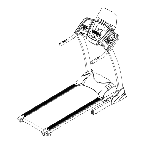
- Page 1 Motorized Treadmill Owner’s Manual AVENGER PLEASE READ ALL INSTRUCTIONS IN THE OWNER'S MANUAL. CAREFULLY BEFORE ASSEMBLY AND USE OF THE TREADMILL, AND KEEP IT FOR FUTURE REFERENCE.
-
Page 2: Table Of Contents
CONTENTS-------------------------------------------------------------------------1 IMPORTANT SAFETY PRECAUTIONS-------------------------------------2 ASSEMBLY INSTRUCTIONS------------------------------------------------3-5 FOLDING& UNFOLDING INSTRUCTIONS------------------------------5-6 INCLINE INSTRUCTIONS----------------------------------------------------6-7 GROUNDING METHODS-------------------------------------------------------7 OPERATIONS GUIDE--------------------------------------------------------8-12 GETTING STARTED GUIDE----------------------------------------------13-14 WARM-UP EXERCISE----------------------------------------------------------14 MOTOR BELT ADJUSTMENT-------------------------------------------------15 MAINTENANCE INSTRUCTIONS----------------------------------------15-16 BELT ADJUSTMENT-------------------------------------------------------------17 EXPLODED DRAWING---------------------------------------------------------18 PARTS LIST--------------------------------------------------------------------19-20 ERROR CODES AND SIGNIFICANCE-------------------------------------21... -
Page 3: Important Safety Precautions
Important Safety Precautions Before starting any exercise Programme, consult with your physician or health professional. This applies especially to persons above 35 years old or to people who have had health problems before. Please do not turn on the power to the Treadmill until assembly is completely finished and the motor cover is attached. -
Page 4: Assembly Instructions
WHEN YOU OPEN THE CARTON, YOU WILL FIND THE PARTS ILLUSTTATED BELOW, IF ANY PARTS ARE MISSING – PLEASE CONTACT YOUR DEALER IMMEDIATELY. 4L/R MAIN FRAME COMPUTER UPRIGHT FRONT 2PCS COVER 2PCS SCREW DRIVER ALLEN WRENCH L POWER PLUG FLAT WASHER 14PCS BOLT M8*15... - Page 5 Step 1: Open the box and put the mainframe on the floor. Connect the COMPUTER MIDDLE WIRE Connector (46) and COMPUTER BOTTOM WIRE Connector (45). Loosely bolt the UPRIGHTS (4L/4R) onto the MAIN FRAME (1) with HALF ROUND HEAD HEX BOLTS (62) and FLAT WASHERS (52).
-
Page 6: Folding& Unfolding Instructions
STEP 3:Put the SAFETY LOCK (76) onto the COMPUTER (7). ATTENTION: Please double check that all assembly steps are completed and that all bolts and screws are tight. Please read these instructions carefully before starting the Treadmill. FOLDING INSTRUCTIONS: Lift up the bed of the machine and continue to lift until you hear a "click" that is made by the safety casing engaging the pneumatic cylinder. -
Page 7: Incline Instructions
UNFOLDING INSTRUCTIONS: Holding the bed of the machine with both hands, use your foot to kick the safety sleeve lightly, to disengage it. Then pull down the bed in the same direction as the arrow. You can now let go of the bed and it will fall slowly and smoothly to the ground. Incline Instructions: Buttons marked 【INCLINE+】... -
Page 8: Grounding Methods
PICTURE B GROUNDING: This product must be grounded. If the machine should malfunction or breakdown, the grounding will provide a path of least resistance for the electric current thus reducing the risk of electric shock. This product is equipped with a power cord having an equipment-grounding conductor and a grounding plug. -
Page 9: Operations Guide
OPERATIONS GUIDE WINDOW DISPLAYS START BUTTON: Press this button to start. After a 5 second countdown, the treadmill will start with the lowest speed of 1KM/H or default speed. STOP BUTTON: Press this button to stop. PROGRAM BUTTON: For choosing your Program - Available Programs are: P01-P12, U1-U2, FAT, HRC... - Page 10 MODE BUTTON: To choose between manual mode and countdown modes: TIME COUNTDOWN, DISTANCE COUNTDOWN and CALORIE COUNTDOWN. SPEED + - BUTTON: SPEED + & SPEED – Set default count; to adjust the speed when treadmill starts, the scope is 0.1 km/Hr in KMH.
- Page 11 Displays the calorie value. Forward count is 0-999 and when reaching 999 it will return to zero. Countdown starts from setting the value to 0, and when countdown is 999, the treadmill will slow down smoothly until stopped. In countdown mode the window will flash to prompt the user to set the calorie value.
- Page 12 SPEED INCLINE SPEED INCLINE SPEED INCLINE SPEED INCLINE SPEED INCLINE Manual Mode parameter setting: Countdown initial setting 15:00 minutes,setting range 5:00---99:00 minutes, stepping 1:00. Countdown calorie initial setting 50 thermal, setting range 10---990 thermal stepping 1. Countdown distance initial setting 1.0km,setting range 0.5---99.9km,stepping 0.1. Cycle switch order is: manual, time, distance, calories.
- Page 13 SAFETY LOCK FUNCTION: The treadmill will stop quickly when the safety lock is taken away. By replacing the safety lock, you can operate the treadmill again immediately. HRC Program When the treadmill stops, press the program to choose the HRC. A: Press “mode”...
-
Page 14: Getting Started Guide
• When all the data is entered, the computer will flash OK and your personal user Program is now saved and ready to use. • When using your user Program the screen will switch from incline to speed and your set Programmed levels will be displayed. -
Page 15: Warm-Up Exercise
EXERCISE FREQUENCY Target is 3--5 times per week, doing 15-60 minutes each time. It is much better to make and keep to a time schedule, and not just exercise when you feel like it. If you feel the need for more strenuous exercise, then please use the speed and incline controls. -
Page 16: Motor Belt Adjustment
toward groin Keep 10-15 seconds, and relax. Repeat 3 times (See picture 5). Maintenance: Checking Belt Tension: If you feel the running belt has occasional pause when you are running, the running belt or motor belt is probably too loose and you’ll need to adjust it. Judgment methods: Step 1: Open the motor cover then let the Treadmill work at the slowest speed. - Page 17 Step 3: Re-tighten the motor attachment bolts and replace the motor cover. WARNING Please make sure to remove the power plug before cleaning or maintaining the Treadmill. CLEANING General cleaning of the unit will greatly prolong the Treadmill's life. ...
-
Page 18: Belt Adjustment
Adjusting the Running Belt: Place the Treadmill on a level surface then set it to run at approximately 6-8 km/h. Observe the running belt deviation to the right or left. If the belt is drifting to the right, unplug the safety lock and power switch, and turn the right adjusting bolt 1/4 turn clockwise, then insert the power switch and safety lock, run the Treadmill and observe the running belt... -
Page 19: Exploded Drawing
EXPLODED DRAWING:... -
Page 20: Parts List
PARTS LIST: DESCRIPTION REMARK DESCRIPTION REMARK MAIN FRAME EDGINGS ∮ ∮ 8.2* 51.5*2 BASE FRAME MOVING WHEEL COMPUTER ADJUSTMENT WHEEL BRACKET MOVING WHEEL PIPE 4L\R UPRIGHT 30*80*t2.0 PLUG MOTOR BRACKET SCREW DRIVER COMPUTER ALLEN WRENCH BOTTOM COVER COMPUTER COVER MIDDLE COVER SYMMET INSTRUCTION PLASTIC FRONT COVER... - Page 21 WIRE COMPUTER MIDDLE ∮ 38*t1.5 INNER PIPE PLUG 1000mm WIRE SENSOR CABLE TIE 100mm MOTOR TOP HEX LOCK NUT COVER CONTROLLER HEX NUT CROSS FLAT HEAD 25L/R END CAP ST4*10 SELF TAPPING BOLT DESCRIPTION REMARK DESCRIPTION REMARK 1 ∮ ∮ SPRING WASHER 8.1* 12.3*t2.1 COMPUTER CHIP...
-
Page 22: Error Codes And Significance
SCREW AND BOTTOM COVER COUNTERSUNK COMPUTER LEFT M6*20 SCREW COVER COUNTERSUNK COMPUTER RIGHT M5*25 SCREW COVER COUNTERSUNK GASKET BOLT M5*10 ST4*15 SELF TAPPING BOLT CROSS FLAT HEAD WIRLESS CHEST ST4*15 SELF TAPPING BOLT BELT RECEIVER Fault Codes and Significances: Fault Code Fault Description Fault Processing Stops and goes into fault Status. - Page 23 Check incline motor sense wire and AC wire are inserted well; AC wire is right inserted according to the indentify in the incline Incline sensor fault motor; make sure the incline motor wire without damager; after check those, press the button on controller, then start self-learning again.
Need help?
Do you have a question about the Avenger and is the answer not in the manual?
Questions and answers