Table of Contents
Advertisement
DA-DHR6802+: Dual 1×4 3-Gb/s/HD / SD
Distribution Amplifiers with Reclocking
DA-DSR6802+: Dual 1×4 SD-SDI Distribution
Amplifiers with Reclocking
DA-DH6802+: Dual 1×4 3-Gb/s/HD / SD
Distribution Amplifiers
DA-DS6802+: Dual 1×4 SD-SDI Distribution
Amplifiers
DA-HR6802+: Single 1×8 3-Gb/s/HD / SD
Distribution Amplifiers with Reclocking
DA-H6802+: Single 1×8 3-Gb/s/HD / SD
Distribution Amplifiers
Installation and Operation Manual
Edition C
175-000386-00
Advertisement
Table of Contents

Related Manuals for Harris DA-DHR6802+


Summary of Contents for Harris DA-DHR6802+
- Page 1 DA-DHR6802+: Dual 1×4 3-Gb/s/HD / SD Distribution Amplifiers with Reclocking DA-DSR6802+: Dual 1×4 SD-SDI Distribution Amplifiers with Reclocking DA-DH6802+: Dual 1×4 3-Gb/s/HD / SD Distribution Amplifiers DA-DS6802+: Dual 1×4 SD-SDI Distribution Amplifiers DA-HR6802+: Single 1×8 3-Gb/s/HD / SD Distribution Amplifiers with Reclocking DA-H6802+: Single 1×8 3-Gb/s/HD / SD Distribution Amplifiers Installation and Operation Manual...
-
Page 3: Installation And Operation Manual
Preliminary—Contents are proprietary and confidential. Do not photocopy or distribute. 6800+ DA-DHR6802+: Dual 1×4 3 Gb/s / HD / SD Distribution Amplifiers with Reclocking DA-DH6802+: Dual 1×4 3 Gb/s/HD / SD Distribution Amplifiers DA-DSR6802+: Dual 1×4 SD-SDI Distribution Amplifiers with Reclocking DA-DS6802+: Dual 1×4 SD-SDI Distribution Amplifiers DA-HR6802+: Single 1×8 3 Gb/s / HD / SD... -
Page 4: Warranty Information
No part of this product or related documentation may be reproduced in any form by any means without prior written authorization of Harris Corporation and its licensors, if any. This publication could include technical inaccuracies or typographical errors. Changes are periodically added to the information herein; these changes will be incorporated into new editions of the publication. -
Page 5: Table Of Contents
Contents Preface Manual Information ................vii Purpose ................... vii Audience ..................vii Revision History ................viii Writing Conventions ............... ix Obtaining Documents ..............ix Unpacking/Shipping Information ............x Safety Standards and Compliances ............xi Safety Terms and Symbols ............. xi Restriction on Hazardous Substances (RoHS) Directive ....xii Waste from Electrical and Electronic Equipment (WEEE) Directive ................. - Page 6 Contents Unpacking the Module ................11 Preparing for Installation ............... 11 Checking the Packing List ............. 12 Setting Jumpers ..................14 Setting J1/J2 Jumpers ..............14 Setting J3 Jumpers ................. 15 Setting J4/J5 Jumpers ..............16 Installing 6800+ Modules ..............18 Required Frames and Back Module Connector Types ....
- Page 7 Contents Power Consumption ................34 Temperature ...................34 Start-Up Time ..................34 Index Keywords ....................35 DA-DHR/DH/DSR/DS/HR/H6802+ Installation and Operation Manual...
- Page 8 Contents DA-DHR/DH/DSR/DS/HR/H6802+ Installation and Operation Manual...
-
Page 9: Preface
Preface Manual Information Purpose This manual details the features, installation procedures, operational procedures, and specifications of the following distribution amplifiers: • DA-DHR6802+ dual 1×4 3-Gb/s / HD / SD distribution amplifiers with reclocking • DA-DH6802+ dual 1×4 3-Gb/s / HD / SD distribution amplifiers •... -
Page 10: Revision History
Preface Revision History Table P-1. Manual Revision History Edition Date Revision History May 2007 Initial release August 2007 Added information about single channel distribution amplifiers October 2007 Removed information about single channel SD-SDI distribution amplifiers viii DA-DHR/DH/DSR/DS/HR/H6802+ Installation and Operation Manual... -
Page 11: Writing Conventions
Preface Writing Conventions To enhance your understanding, the authors of this manual have adhered to the following text conventions: Table P-2. Manual Style and Writing Conventions Term or Description Convention Bold Indicates dialog boxes, property sheets, fields, buttons, check boxes, list boxes, combo boxes, menus, submenus, windows, lists, and selection names. -
Page 12: Unpacking/Shipping Information
Preface Unpacking/Shipping Information This product was carefully inspected, tested, and calibrated before shipment to ensure years of stable and trouble free service. 1. Check equipment for any visible damage that may have occurred during transit. 2. Confirm that you have received all items listed on the packing list. 3. -
Page 13: Safety Standards And Compliances
Preface Safety Standards and Compliances See the 6800+ Safety Instructions and Standards Manual to find the safety standards and compliances for this 6800+ series product. A safety manual is shipped with every FR6802+ Frame Installation and Operation Manual and can be downloaded from our website. Alternatively, contact your Customer Service representative for a copy of this safety manual. -
Page 14: Restriction On Hazardous Substances (Rohs) Directive
Preface Restriction on Hazardous Substances (RoHS) Directive Directive 2002 / 95 / EC—commonly known as the European Union (EU) Restriction on Hazardous Substances (RoHS)—sets limits on the use of certain substances found in electrical and electronic equipment. The intent of this legislation is to reduce the amount of hazardous chemicals that may leach out of landfill sites or otherwise contaminate the environment during end-of-life recycling. -
Page 15: Waste From Electrical And Electronic Equipment (Weee) Directive
Preface Waste from Electrical and Electronic Equipment (WEEE) Directive The European Union (EU) Directive 2002 / 96 / EC on Waste from Electrical and Electronic Equipment (WEEE) deals with the collection, treatment, recovery, and recycling of electrical and electronic waste products. - Page 16 Preface DA-DHR/DH/DSR/DS/HR/H6802+ Installation and Operation Manual...
-
Page 17: Overview
Preliminary—Contents are proprietary and confidential. Do not photocopy or distribute. Chapter 1 Introduction Overview The following topics are described in this chapter: • “Main Features” on page 2 • “Module Descriptions” on page 5 • “Product Description” on page 2 •... -
Page 18: Product Description
Preliminary—Contents are proprietary and confidential. Do not photocopy or distribute. Chapter 1: Introduction Product Description The DA-DHR/DH/DSR/DS/HR/H6802+ series of distribution amplifiers are designed to distribute serial digital video signals according to SMPTE 257C, 292M, 424M, DVB, and other related standards. They feature high reliability, excellent video performance, and low cost. - Page 19 Preliminary—Contents are proprietary and confidential. Do not photocopy or distribute. Chapter 1: Introduction • Re-lockable for DVB-ASI signal • Reclock status and rate report by LEDs • Reclocking Bypass mode is selectable as automatic or enforced • Card edge control by jumpers with LED display •...
-
Page 20: Typical Broadcast And Production Applications
Preliminary—Contents are proprietary and confidential. Do not photocopy or distribute. Chapter 1: Introduction • Enable automatic switching input between input 1 and input 2 in the 1×8 configuration when a loss of the input signal is detected. • Input signal presence detect and report •... -
Page 21: Module Descriptions
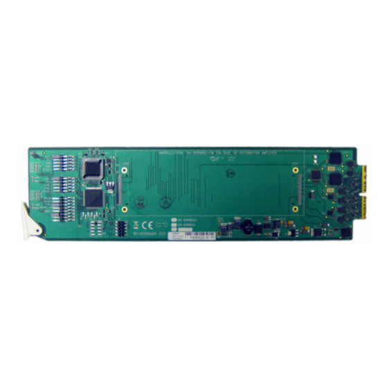
Preliminary—Contents are proprietary and confidential. Do not photocopy or distribute. Chapter 1: Introduction Module Descriptions Front Module Figure 1-1 is a generic top-front view of a typical front module. See Figure 3-1 on page 20 for jumper locations; see Figure 3-2 on page 27 Figure 3-3 on page 28 for LED locations. - Page 22 Preliminary—Contents are proprietary and confidential. Do not photocopy or distribute. Chapter 1: Introduction SDI OUT 1 SDI OUT 2 Figure 1-2. Back Module for FR6802+X(F) Frame DA-DHR/DH/DSR/DS/HR/H6802+ Installation and Operation Manual...
-
Page 23: Signal Flow
Preliminary—Contents are proprietary and confidential. Do not photocopy or distribute. Chapter 1: Introduction Signal Flow OUT 1 Inverter IN 1 Reclocker Driver Inverter EQ_A RCLK_A DRV_A OUT 2 Inverter Driver Reclocker IN 2 4×4 Inverter EQ_B RCLK_B DRV_B Streaming Trans- Streaming sub-board ceiver... - Page 24 Preliminary—Contents are proprietary and confidential. Do not photocopy or distribute. Chapter 1: Introduction DA-DHR/DH/DSR/DS/HR/H6802+ Installation and Operation Manual...
-
Page 25: Overview
Preliminary—Contents are proprietary and confidential. Do not photocopy or distribute. Chapter 2 Installation Overview This chapter describes DA-DHR/DH/DSR/DS/HR/H6802+ modules’ installation process, including the following topics: • “Installing Modules” on page 18 • “Making Connections” on page 18 • “Maximum 6800+ Frame Power Ratings” on page 10 •... -
Page 26: Maximum 6800+ Frame Power Ratings
Preliminary—Contents are proprietary and confidential. Do not photocopy or distribute. Chapter 2: Installation Maximum 6800+ Frame Power Ratings Power consumption information is listed in Chapter 4: “Specifications” on page Table 2-1 describes the maximum allowable power ratings for 6800+ frames. Note the given maximums before installing any 6800+ modules in your frame. -
Page 27: Unpacking The Module
Preliminary—Contents are proprietary and confidential. Do not photocopy or distribute. Chapter 2: Installation Unpacking the Module Preparing for Installation Before you install DA-DHR/DH/DSR/DS/HR/H6802+ modules, perform the following: • Check the equipment for any visible damage that may have Note occurred during transit. •... -
Page 28: Checking The Packing List
• One DA-DHR6802+ front module DA-DHR6802+ • One standard double-slot back connector • One DA-DHR/DH/DSR/DS/HR/H6802+ Installation and Operation Manual • One standard double-slot back connector DA-DHR6802+DR DA-DH6802+ Distribution Amplifier Modules • One DA-DH6802+ front module DA-DH6802+ • One DA-DHR/DH/DSR/DS/HR/H6802+ Installation and Operation Manual •... - Page 29 Preliminary—Contents are proprietary and confidential. Do not photocopy or distribute. Chapter 2: Installation Table 2-3. Single 1×8 Distribution Amplifier Modules Packing List Ordered Product Content Description with Reclocking DA-HR6802+ Distribution Amplifier Modules • One DA-HR6802+ front module DA-HR6802+ • One DA-DHR/DH/DSR/DS/HR/H6802+ Installation and Operation Manual •...
-
Page 30: Setting Jumpers
Preliminary—Contents are proprietary and confidential. Do not photocopy or distribute. Chapter 2: Installation Setting Jumpers Setting J1/J2 Jumpers The J1 and J2 jumpers are used to select local control reclock setting. Follow this procedure to set the jumpers: 1. Locate the J1 and J2 jumper sets on the module. Figure 2-1 shows Note... -
Page 31: Setting J3 Jumpers
Preliminary—Contents are proprietary and confidential. Do not photocopy or distribute. Chapter 2: Installation Setting J3 Jumpers The J3 jumper is used to set channel configuration, control mode, and Note enabling input backup. Follow this procedure to set the jumper: 1. Locate jumper set J3 on the module. Figure 2-2 shows the standard You need to configure modules... -
Page 32: Setting J4/J5 Jumpers
Preliminary—Contents are proprietary and confidential. Do not photocopy or distribute. Chapter 2: Installation Setting J4/J5 Jumpers The J4 and J5 jumpers are used to set the output slew rate control. Follow this procedure to set the jumpers: 1. Locate the J3 and J4 jumper sets on the module. Figure 2-3 shows the standard location of the jumper sets. - Page 33 Preliminary—Contents are proprietary and confidential. Do not photocopy or distribute. Chapter 2: Installation 2. Place a jumper on the pins that correspond to the slew rate you want. See Table 2-4. Table 2-4. J4/J5 Jumper Set Settings Slew Rate Settings Modules Using this Setting Automatic Reclockable input signal in...
-
Page 34: Installing 6800+ Modules
Preliminary—Contents are proprietary and confidential. Do not photocopy or distribute. Chapter 2: Installation Installing 6800+ Modules Required Frames and Back Module Connector Types These modules have double-width back connectors that can be installed in an FR6802+ series frame. See the FR6802+ Frame Installation and Operation Manual for details on installing back connectors in an FR6802+ frame. -
Page 35: Overview
Preliminary—Contents are proprietary and confidential. Do not photocopy or distribute. Chapter 3 Operation Overview This chapter describes how to operate DA-DHR/DH/DSR/DS/HR/ H6802+ modules using local controls only. See the following documents for information on how to operate this product remotely: + Pilot Lite™... -
Page 36: Operating Notes
Preliminary—Contents are proprietary and confidential. Do not photocopy or distribute. Chapter 3: Operation Operating Notes When you change a control parameter on a DA-DHR/DH/DSR/DS/HR/ H6802+ module, the effect is immediate. However, the module requires up to 20 seconds to save the latest change. After 20 seconds, the new settings are saved and will be restored if the module loses power and must be restarted. -
Page 37: J1/J2 Jumpers
Preliminary—Contents are proprietary and confidential. Do not photocopy or distribute. Chapter 3: Operation J1/J2 Jumpers You can use the J1 (for channel 1 control) or J2 (for channel 2 control) jumper to select local control reclock setting. Figure 3-1 on page 20 illustrates the location of these jumpers. -
Page 38: Understanding Parameter Types
Preliminary—Contents are proprietary and confidential. Do not photocopy or distribute. Chapter 3: Operation • Manual-high slew rate: for DA-DH6802+ and DA-H6802+; or for non-reclockable input signal in DA-DHR6802+ and DA-HR6802+ modules • Manual-low slew rate: for DA-DH6802+ and DA-H6802+; or for non-reclockable input signal in DA-DHR6802+ and DA-HR6802+ modules J4/J5 jumper settings are not required for DA-DSR6802+, DA-... -
Page 39: Setting Locally Controlled Parameters
+ Pilot Lite control screen; however, you cannot change any setting in this mode via + Pilot Lite. Harris recommends that you use (To control the reclocking setting mode via + Pilot Lite, set the J3 the available 6800+ software jumper to the remote control reclock setting operation mode.) -
Page 40: Setting Remotely Controlled Parameters
Preliminary—Contents are proprietary and confidential. Do not photocopy or distribute. Chapter 3: Operation Setting Remotely Controlled Parameters Table 3-2 Table 3-3 on page 25 describe parameters that are accessible remotely. See your CCS control software application manual or online help for more information on setting and monitoring these parameters remotely. - Page 41 Preliminary—Contents are proprietary and confidential. Do not photocopy or distribute. Chapter 3: Operation Table 3-3. DA-DHR6802+, DA-DSR6802+, DA-HR6802+ Remotely Controlled Parameters Name Range Description • 0 = Disable Backup mode Loss of signal (input 1) switching enable, • 1 = Enable automatically switch both output MUXs to select input 2 when input 1 has lost its input signal •...
-
Page 42: Changing Parameter Settings
Preliminary—Contents are proprietary and confidential. Do not photocopy or distribute. Chapter 3: Operation Changing Parameter Settings You can change module parameter settings locally with the card-edge jumper or remotely by selecting the Reclocking Mode parameter setting. Recalling Default Parameter Settings You cannot recall default parameter settings for DA-DHR/DH/DSR/ DS/HR/H6802+ modules. -
Page 43: Leds And Alarms
Preliminary—Contents are proprietary and confidential. Do not photocopy or distribute. Chapter 3: Operation LEDs and Alarms Module Status Indicator LED Figure 3-2. Module Status Indicator LED A module status LED reports the state of the module. See Figure 3-1 on page 20 for the location of this LED, and Table 3-4... -
Page 44: Module-Specific Leds
Preliminary—Contents are proprietary and confidential. Do not photocopy or distribute. Chapter 3: Operation Module-Specific LEDs Figure 3-3. Module-Specific LEDs Each 6800+ module has a number of LEDs assigned to indicate varying states / functions. These functions are listed in Table 3-5. -
Page 45: Alarms
Preliminary—Contents are proprietary and confidential. Do not photocopy or distribute. Chapter 3: Operation Alarms Alarms are usually logged and monitored within the available 6800+ software control applications (for example, + Pilot Lite or Pilot). See the appropriate software control user manual or online help for more information. - Page 46 Preliminary—Contents are proprietary and confidential. Do not photocopy or distribute. Chapter 3: Operation DA-DHR/DH/DSR/DS/HR/H6802+ Installation and Operation Manual...
-
Page 47: Overview
Preliminary—Contents are proprietary and confidential. Do not photocopy or distribute. Chapter 4 Specifications Overview The following specification tables appear in this chapter: • “Inputs” on page 32 • “Outputs” on page 33 • “Power Consumption” on page 34 • “Performance” on page 34 •... -
Page 48: Inputs
Preliminary—Contents are proprietary and confidential. Do not photocopy or distribute. Chapter 4: Specifications Inputs Table 4-1. Input Specifications Item Specification Number of inputs Dual channel mode 1 each channel Single channel mode Signal type 3.0 G, HD, SD, ASI Connector BNC per IEC169-8 Impedance 75Ω... -
Page 49: Outputs
Preliminary—Contents are proprietary and confidential. Do not photocopy or distribute. Chapter 4: Specifications Outputs Table 4-2. Output Specifications Item Specification Number of outputs Dual channel mode 4 each channel Single channel mode Signal type 3.0G, HD, SD, ASI Connector BNC per IEC169-8 Impedance 75Ω... -
Page 50: Performance
Preliminary—Contents are proprietary and confidential. Do not photocopy or distribute. Chapter 4: Specifications Performance Table 4-3. Performance Specifications Item Specification Jitter 0.2 UI for reclocking DA 0.3 UI for non-reclocking DA (reference only) Propagation ~ 4.0 ns (for reference only) Power Consumption Module power consumption is <... -
Page 51: Keywords
Index Keywords power consumption start-up time Adjustable parameters temperature specifications Alarms DA-DHR6802+ Applications alarms Back connectors. See Back modules applications Back modules 5–6, 18 description Backup_EN switch back module 5–6 Changing parameter settings features 2–3 Channel configuration switch front module Controls product control types... - Page 52 Index product remote parameters LEDs setting jumpers 14–17, 20–21 packing list signal flow remote parameters specifications setting jumpers 14–17, 20–21 input specifications signal flow output specifications specifications performance specifications input specifications power consumption output specifications start-up time performance specifications temperature specifications power consumption DA-HR6802+ start-up time...
- Page 53 Index Waste from Electrical and Electronic Equipment module status xiii Local control jumpers Features 2–4 Locally controlled parameter list Front modules Manual information vii–ix Hardware versions, reading Modes. See Reclock modes Modules 1×4 (dual) configurations. See DA-DHR/DH/ DSR/DS6802+ Input specifications 1×8 (single) configurations.
- Page 54 Index lists 23, 24–25 Safety locally controlled compliances parameter types RoHS directive read-only standards recalling settings symbols remotely controlled 24–25 terms setting parameters 23–25 WEEE directive xiii Performance specifications Setting jumpers Performance temperature Shipping information Power consumption specifications Signal flow diagrams Power ratings Software versions, reading Power up time...
Need help?
Do you have a question about the DA-DHR6802+ and is the answer not in the manual?
Questions and answers