
Related Manuals for Harris VCA6800+


Summary of Contents for Harris VCA6800+
- Page 1 VCA/VDA/VEA6800+ Analog Video Distribution Amplifiers Installation and Operation Manual Edition D 175-000181-00...
-
Page 3: Installation And Operation
Preliminary—Contents are proprietary and confidential. Do not photocopy or distribute. VCA 6800+ VDA6800+ VEA6800+ Analog Video Distribution Amplifier Installation and Operation Manual Edition D July 2007... -
Page 4: Warranty Information
No part of this product or related documentation may be reproduced in any form by any means without prior written authorization of Harris Corporation and its licensors, if any. This publication could include technical inaccuracies or typographical errors. Changes are periodically added to the information herein; these changes will be incorporated into new editions of the publication. -
Page 5: Table Of Contents
Preliminary—Contents are proprietary and confidential. Do not photocopy or distribute. Contents Preface Manual Information ................vii Purpose ................... vii Audience ..................vii Revision History ................vii Writing Conventions ..............viii Obtaining Documents ..............viii Unpacking / Shipping Information ............ix Safety Standards and Compliances ............x Safety Terms and Symbols ...............x Restriction on Hazardous Substances (RoHS) Directive .... - Page 6 Preliminary—Contents are proprietary and confidential. Do not photocopy or distribute. Contents Unpacking the Module ................15 Preparing the Product for Installation ..........15 Checking the Packing List ............. 15 Setting Jumpers and Adjustable Components ........17 VCA6800+ ..................17 VDA6800+ ..................20 VEA6800+ ..................
-
Page 7: Preface
Preliminary—Contents are proprietary and confidential. Do not photocopy or distribute. Preface Manual Information Purpose This manual details the features, installation procedures, operational procedures, and specifications of the VCA / VDA / VEA6800+ analog video distribution amplifiers. Audience This manual is written for engineers, technicians and operators responsible for the installation, setup, and / or operation of the VCA / VDA / VEA6800+ analog video distribution amplifiers. -
Page 8: Writing Conventions
Preliminary—Contents are proprietary and confidential. Do not photocopy or distribute. Preface Writing Conventions To enhance your understanding, the authors of this manual have adhered to the following text conventions: Table P-2. Manual Style and Writing Conventions Term or Description Convention Bold Indicates dialog boxes, property sheets, fields, buttons, check boxes, list boxes, combo boxes, menus, submenus,... -
Page 9: Unpacking / Shipping Information
Preliminary—Contents are proprietary and confidential. Do not photocopy or distribute. Preface Unpacking / Shipping Information This product was carefully inspected, tested, and calibrated before shipment to ensure years of stable and trouble free service. 1. Check equipment for any visible damage that may have occurred during transit. -
Page 10: Safety Standards And Compliances
Preliminary—Contents are proprietary and confidential. Do not photocopy or distribute. Preface Safety Standards and Compliances See the 6800+ Safety Instructions and Standards Manual to find the safety standards and compliances for this 6800+ series product. A safety manual is shipped with every FR6802+ Frame Installation and Operation Manual and can be downloaded from our website. -
Page 11: Restriction On Hazardous Substances (Rohs) Directive
Preliminary—Contents are proprietary and confidential. Do not photocopy or distribute. Preface Restriction on Hazardous Substances (RoHS) Directive Directive 2002/95/EC—commonly known as the European Union (EU) Restriction on Hazardous Substances (RoHS)—sets limits on the use of certain substances found in electrical and electronic equipment. The intent of this legislation is to reduce the amount of hazardous chemicals that may leach out of landfill sites or otherwise contaminate the environment during end-of-life recycling. -
Page 12: Waste From Electrical And Electronic Equipment (Weee) Directive
Preliminary—Contents are proprietary and confidential. Do not photocopy or distribute. Preface Waste from Electrical and Electronic Equipment (WEEE) Directive The European Union (EU) Directive 2002/96/EC on Waste from Electrical and Electronic Equipment (WEEE) deals with the collection, treatment, recovery, and recycling of electrical and electronic waste products. -
Page 13: Overview
Preliminary—Contents are proprietary and confidential. Do not photocopy or distribute. Chapter 1 Introduction Overview This chapter introduces the VCA / VDA / VEA6800+, and includes the following topics: The following topics are described in this chapter: • “Block Diagrams” on page 11 •... -
Page 14: Product Description
Preliminary—Contents are proprietary and confidential. Do not photocopy or distribute. Chapter 1: Introduction Product Description The VCA / VDA / VEA6800+ is an analog video distribution amplifier set in the new 6800+ family. These DAs feature high video performance, low cost, and remote control. - Page 15 Preliminary—Contents are proprietary and confidential. Do not photocopy or distribute. Chapter 1: Introduction Module presence reporting via +Pilot Lite control system • • Hot swappable VDA6800+ The VDA6800+ is a high performance, cost efficient, general purpose analog video distribution amplifier. Composite and component analog NTSC, PAL, SECAM signals (with sync or without sync), subcarrier, and coaxial version AES digital audio signals can be amplified with the VDA6800+ in FR6802+ series frames.
- Page 16 Preliminary—Contents are proprietary and confidential. Do not photocopy or distribute. Chapter 1: Introduction • Looping and internal terminating selectable with dual slot back module, internal terminating with single slot back module with FR6802+X(F) frames; looping or internal terminating selectable with FR6802+DM(F) frames (see Figure 2-10 on page 22 instructions on setting this jumper) •...
-
Page 17: Module Descriptions
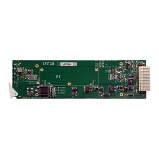
Preliminary—Contents are proprietary and confidential. Do not photocopy or distribute. Chapter 1: Introduction Module Descriptions Front Module VCA6800+ Figure 1-1 is a generic top-front view of a typical VCA6800+ front module. See Figure 2-1 on page 17 for jumper and adjustment locations. - Page 18 Preliminary—Contents are proprietary and confidential. Do not photocopy or distribute. Chapter 1: Introduction VEA6800+ Figure 1-3 is a generic top-front view of a typical VEA6800+ front module. See Figure 2-9 on page 22 for jumper and adjustment locations. Figure 1-3. Typical VEA6800+ Front Module The VEA6800+ can compensate for various cable types using different equalization network submodules installed in the main module.The following modules are available:...
-
Page 19: Feature Description
Preliminary—Contents are proprietary and confidential. Do not photocopy or distribute. Chapter 1: Introduction LEDs, Switches, and Jumpers Table 1-2 briefly describes generic 6800+ LEDs, switches, and jumpers. See Chapter 2: “Installation and Configuration” for more information on specific VCA / VDA / VEA6800+ module controls, LEDs, and jumpers. - Page 20 Preliminary—Contents are proprietary and confidential. Do not photocopy or distribute. Chapter 1: Introduction Table 1-3. VCA / VDA / VEA6800+ Module-Specific Status LEDs Condition Color Function Confidence Amber Received data eye opening less than half a flag error bit period, indicating a possible lack of signal strength or high jitter;...
-
Page 21: Back Modules
Preliminary—Contents are proprietary and confidential. Do not photocopy or distribute. Chapter 1: Introduction Back Modules FR6802+ Frame Back Module Figure 1-4 shows the single-width back connector module and Figure 1-5 shows the double-slot back connector module used by the VCA / VDA / VEA6800+ when installed in an FR6802+ frame. Figure 1-4. - Page 22 Preliminary—Contents are proprietary and confidential. Do not photocopy or distribute. Chapter 1: Introduction Signal Input/Output Connections for FR6802+DM Frames Figure 1-6 shows the signal input/output connections used by the Note VCA / VDA / VEA6800+ when installed in an FR6802+DM frame. In a DM frame, you can create looping inputs by adding a T-connector on the input...
-
Page 23: Block Diagrams
Preliminary—Contents are proprietary and confidential. Do not photocopy or distribute. Chapter 1: Introduction Block Diagrams Input Output Cable equalizer differential driver amplifier Gain Termi- nation select Clamp Clamp mode select Figure 1-8. VCA6800+ Block Diagram Figure 1-9. VDA6800+ Block Diagram VCA / VDA / VEA6800+ Installation and Operation Manual... - Page 24 Preliminary—Contents are proprietary and confidential. Do not photocopy or distribute. Chapter 1: Introduction Figure 1-10. VEA6800+ Block Diagram VCA / VDA / VEA6800+ Installation and Operation Manual...
-
Page 25: Overview
Preliminary—Contents are proprietary and confidential. Do not photocopy or distribute. Chapter 2 Installation and Configuration Overview This chapter describes the VCA / VDA / VEA6800+ installation process, Caution including the following topics: • “Maximum 6800+ Frame Power Ratings” on page 14 Before installing this product, read the 6800+ Series Safety •... -
Page 26: Maximum 6800+ Frame Power Ratings
Preliminary—Contents are proprietary and confidential. Do not photocopy or distribute. Chapter 2: Installation and Configuration Maximum 6800+ Frame Power Ratings Table 2-1 describes the maximum allowable power ratings for 6800+ frames.Note the given maximums before installing any 6800+ modules in your frame. VCA/VDA/VEA6800+ modules can be installed in FR6802+ frames and 6000/7000 series frames. -
Page 27: Unpacking The Module
VCA6800+ • One VCA / VDA / VEA6800+ Installation and Operation Manual • One VCA6800+ front module VCA6800+S • One standard single-slot back connector • One VCA / VDA / VEA6800+ Installation and Operation Manual • One VCA6800+ front module VCA6800+D •... - Page 28 Preliminary—Contents are proprietary and confidential. Do not photocopy or distribute. Chapter 2: Installation and Configuration Table 2-2. VCA/VDA/VEA6800+ Packing List (Continued) Ordered Product Content Description • One VDA6800+ front module VDA6800+S • One standard single-slot back connector • One VCA / VDA / VEA6800+ Installation and Operation Manual •...
-
Page 29: Setting Jumpers And Adjustable Components
Preliminary—Contents are proprietary and confidential. Do not photocopy or distribute. Chapter 2: Installation and Configuration Setting Jumpers and Adjustable Components VCA6800+ The VCA6800+ module has four jumpers, which are used to select the following modes: • One jumper for looping or internal input termination •... - Page 30 Preliminary—Contents are proprietary and confidential. Do not photocopy or distribute. Chapter 2: Installation and Configuration Setting the Input Terminating Jumper Follow this procedure to set the jumper for looping or internal input Note termination: 1. Locate the jumper block on the module. Figure 2-1 on page 17 In a DM frame, you can create looping inputs by adding a...
- Page 31 Preliminary—Contents are proprietary and confidential. Do not photocopy or distribute. Chapter 2: Installation and Configuration Setting the Clamping Mode Follow this procedure to set the jumper for soft-, hard- or no-clamping mode: 1. Locate the jumper block on the module. Figure 2-1 on page 17 shows the location of this jumper block.
-
Page 32: Vda6800
Preliminary—Contents are proprietary and confidential. Do not photocopy or distribute. Chapter 2: Installation and Configuration VCA6800+ Decrease Increase Figure 2-5. VCA6800+ Gain and EQ Mode Potentiometer Adjustment A single-turn pot allows fine adjustment of the CMR. A separate single-turn pot controls the response, while a variable capacitor controls EQ response. - Page 33 Preliminary—Contents are proprietary and confidential. Do not photocopy or distribute. Chapter 2: Installation and Configuration Setting the Input Terminating Jumper Follow this procedure to set the jumper for looping or internal input Note termination: 1. Locate the jumper block on the module. Figure 2-6 on page 20 In a DM frame, you can create looping inputs by adding a...
-
Page 34: Vea6800
Preliminary—Contents are proprietary and confidential. Do not photocopy or distribute. Chapter 2: Installation and Configuration VEA6800+ The VEA6800+ module has one jumper, which is used to select the looping or internal input terminating. The VEA6800+ module also has adjustable pots for gain and EQ modes. - Page 35 Preliminary—Contents are proprietary and confidential. Do not photocopy or distribute. Chapter 2: Installation and Configuration Adjusting Potentiometers The VEA6800+ module has two separate, adjustable potentiometers (“pots”) for gain and EQ mode adjustment. Figure 2-9 on page 22 shows the location of these pots. A multi-turn pot allows you to adjust gain for a range of –3 dB to +3 dB.
-
Page 36: Installing 6800+ Modules
Preliminary—Contents are proprietary and confidential. Do not photocopy or distribute. Chapter 2: Installation and Configuration Installing 6800+ Modules Required Frames and Back Connector Types The VCA/VDA/VEA6800+ modules have single- and double-width back connectors that can be installed in an FR6802+X(F) or a 6800/ 7000 series frame. -
Page 37: Overview
Preliminary—Contents are proprietary and confidential. Do not photocopy or distribute. Chapter 3 Specifications Overview The following specification tables appear in this chapter: • “Inputs” on page 26 through page 27 • “Outputs” on page 28 • “Performance” on page 29 through page 31 •... -
Page 38: Inputs
Preliminary—Contents are proprietary and confidential. Do not photocopy or distribute. Chapter 3: Specifications Inputs Table 3-1. VCA6800+ Input Specifications Item Specification Number of inputs Video input level 1Vp-p nominal Maximum input level 2.5 Vp-p centered at 0 V Input impedance 75Ω... -
Page 39: Inputs" On Page 26 Through
Preliminary—Contents are proprietary and confidential. Do not photocopy or distribute. Chapter 3: Specifications Table 3-3. VEA6800+ Input Specifications Item Specification Number of inputs Video input level 1Vp-p nominal Maximum input level 2.5 Vp-p centered at 0 V Input impedance 75Ω looping or internal terminating selectable Coupling Input return loss... -
Page 40: Outputs
Preliminary—Contents are proprietary and confidential. Do not photocopy or distribute. Chapter 3: Specifications Outputs Table 3-4. VCA6800+ Output Specifications Item Specification Number of outputs 4 or 8 Output impedance 75Ω Output return loss > 45 dB to 5 MHz > 40 dB to 10 MHz Output isolation >... -
Page 41: Performance
Preliminary—Contents are proprietary and confidential. Do not photocopy or distribute. Chapter 3: Specifications Performance Table 3-7. VCA6800+ Performance Specifications Item Specification Gain range – 3 dB to + 3 dB Frequency response < ± 0.05 dB DC–10 MHz < ± 0.2 dB to 20 MHz –3 dB >... - Page 42 Preliminary—Contents are proprietary and confidential. Do not photocopy or distribute. Chapter 3: Specifications Table 3-8. VDA6800+ Performance Specifications Item Specification Gain range – 3 dB to + 3 dB Frequency response < ± 0.05 dB DC–10 MHz < ± 0.2 dB to 20 MHz –3 dB >...
-
Page 43: Performance" On Page 29 Through
Preliminary—Contents are proprietary and confidential. Do not photocopy or distribute. Chapter 3: Specifications Table 3-9. VEA6800+ Performance Specifications Item Specification Gain range – 3 dB to + 3 dB Frequency response < ± 0.05 dB DC–10 MHz < ± 0.2 dB to 20 MHz –3 dB >... -
Page 44: Propagation Delay
Preliminary—Contents are proprietary and confidential. Do not photocopy or distribute. Chapter 3: Specifications Propagation Delay Table 3-10. Propagation Delay Specifications Item Specification VCA6800+ 15 ± 1.0 ns VDA6800+ 14 ± 1.0 ns VEA6800+ 15 ± 1.0 ns Temperature Table 3-11. Temperature Specifications Item Specification Performance temperature... -
Page 45: Keywords
Index Keywords jumpers LEDs Adjustable components 17–23 switches Adjusting potentiometers VCA6800+ VCA6800+ 19–20 VDA6800+ VDA6800+ VEA6800+ VEA6800+ Applications Back modules 9–10, 24 Input specifications Block diagrams VCA6800+ VCA6800+ VDA6800+ VDA6800+ VEA6800+ VEA6800+ Input terminating jumper Cable types VCA6800+ Clamping mode VDA6800+ Coupling mode VEA6800+... - Page 46 Index Introduction VDA6800+ applications VEA6800+ block diagrams 11–12 Power ratings VCA6800+ Preparing for installation VDA6800+ Product description 2–4 VEA6800+ Product equalization cable types descriptions modules 5–8 product 2–4 Removing modules features Restriction on Hazardous Substances (RoHS) VCA6800+ 2–3 directive VDA6800+ Safety VEA6800+ 3–4...
- Page 47 Index packing list output setting adjustable components 17–20 performance setting jumpers 17–20 VEA6800+ specifications adjusting potentiometers input block diagram output cable types performance features 3–4 VDA6800+ input terminating jumper adjusting potentiometers packing list block diagram specifications features input input terminating jumper output packing list 15–16...
- Page 48 Index VCA / VDA / VEA6800+ Installation and Operation Manual...
Need help?
Do you have a question about the VCA6800+ and is the answer not in the manual?
Questions and answers