TSI Instruments VELOCICALC 9565 Series Operation And Service Manual
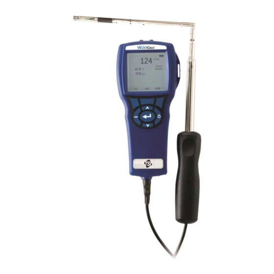
Air velocity meter
Hide thumbs
Also See for VELOCICALC 9565 Series:
- Operation and service manual (47 pages) ,
- Operation and service manual (49 pages) ,
- Operation and service manual (48 pages)

Related Manuals for TSI Instruments VELOCICALC 9565 Series


Summary of Contents for TSI Instruments VELOCICALC 9565 Series
- Page 1 VELOCICALC ® AIR VELOCITY METER MODEL 9565 SERIES OPERATION AND SERVICE MANUAL P/N 6004851, REVISION F JUNE 2018 GlobalTestSupply www. .com Find Quality Products Online at: sales@GlobalTestSupply.com...
- Page 2 Copyright TSI Incorporated / 2011-2018 / All rights reserved. Limitation Of Warranty And Liability (effective February 2015) Seller warrants the goods, excluding software, sold hereunder, under normal use and service as described in the operator's manual, to be free from defects in workmanship and material for 24 months, or if less, the length of time specified in the operator's manual, from the date of shipment to the customer.
- Page 3 INJURIES, OR DAMAGES CONCERNING THE GOODS (INCLUDING CLAIMS BASED ON CONTRACT, NEGLIGENCE, TORT, STRICT LIABILITY OR OTHERWISE) SHALL BE THE RETURN OF GOODS TO SELLER AND THE REFUND OF THE PURCHASE PRICE, OR, AT THE OPTION OF SELLER, THE REPAIR OR REPLACEMENT OF THE GOODS. IN THE CASE OF SOFTWARE, SELLER WILL REPAIR OR REPLACE DEFECTIVE SOFTWARE OR IF UNABLE TO DO SO, WILL REFUND THE PURCHASE PRICE OF THE SOFTWARE.
-
Page 4: Table Of Contents
CONTENTS CHAPTER 1 UNPACKING AND PARTS IDENTIFICATION ..... 1 Bluetooth ® Safety and Compliance..........1 CHAPTER 2 SETTING-UP ..............5 Supplying Power to the Model 9565 Series ........5 Installing the Batteries ............... 5 DIP Switch Settings ..............5 Using the AC Adapter ..............6 Connecting Ventilation or IAQ Probes .......... - Page 5 ZERO CO ..................33 APPLICATIONS ................. 34 CALIBRATION .................. 35 BLUETOOTH FUNCTIONS (Models 9565-P and 9565-X only) ..... 35 Discover Devices ..............35 Discoverability ................36 PINcode ................... 36 # AutoConnects ............... 36 Printing Data Using the Portable Printer (Models 9565-P and 9565-X only) ................
-
Page 6: Chapter 1 Unpacking And Parts Identification
Chapter 1 Unpacking and Parts Identification Carefully unpack the instrument and accessories from the shipping container. Check the individual parts against the list of components below. If anything is missing or damaged, notify TSI immediately. 1. Carrying case 2. Instrument 3. - Page 7 NO T E This device may not cause interference; this device must accept any interference, including interference that may cause undesired operation of the device. l’appareil ne doit pas produire de brouillage; l’appareil doit accepter tout brouillage radioélectrique subi, même si le brouillage est susceptible d’en compromettre le fonctionnement.
- Page 8 W A R N I N G Changes or modifications not expressly approved by the party responsible for compliance could void the user's authority to operate the equipment. GlobalTestSupply www. .com Find Quality Products Online at: sales@GlobalTestSupply.com...
-
Page 9: Chapter 2 Setting-Up
Chapter 2 Setting-up Supplying Power to the Model 9565 Series The Model 9565 VelociCalc Air Velocity Meter can be powered in ® one of two ways: four size AA batteries or the AC adapter. Installing the Batteries Insert four AA batteries as indicated by the diagram located on the inside of the battery compartment. -
Page 10: Using The Ac Adapter
DO NOT attempt to charge alkaline batteries. Using the AC Adapter The AC adapter can be used to power the instrument or to charge the NiMH batteries when the DIP switch in the battery compartment is set to NiMH. If the DIP switch is set to Alkaline, and the AC power adapter is connected, then the batteries will be bypassed and the meter will be powered by the AC adapter. -
Page 11: Connecting Ventilation Or Iaq Probes
Connecting Ventilation or IAQ Probes The ventilation and IAQ probes have a “D” shape overmolding on the mini-DIN connector which must align with the connector at the base of the 9565 series meter. This will ensure the probe is properly connected and remains so during use. -
Page 12: Using The Pressure Ports (9565-P)
DO NOT use the instrument or probes near hazardous voltage sources since serious injury could result. Using the Pressure Ports (9565-P) The 9565-P includes pressure ports that can be used to measure static and differential pressures in ductwork. Negative (-) Pressure Port Positive (+) Pressure Port Connecting the Static Pressure Probe The Static Pressure probe included with the 9565-P is connected... -
Page 13: Connecting An Optional Pitot Probe Or Airflow (Straight Pitot) Probe
Connecting an Optional Pitot Probe or Airflow (straight pitot) Probe When connected to a pitot probe, air velocity or air volume can be measured. A pitot probe can be connected to the “+” and “-” pressure ports on the Model 9565-P using two pieces of tubing of equal length. -
Page 14: Thermocouple Ports
DO NOT use the instrument or probes near hazardous voltage sources since serious injury could result. Thermocouple Ports The 9565 series includes two thermocouple ports at the base of the meter. Any K-Alloy thermocouple with mini-connector can be attached. See Display Setup for setting the thermocouple temperature readings to be displayed as TC1, TC2, or TC1-TC2. -
Page 15: Connecting The Optional Bluetooth Portable Printer Device (Models 9565-P And 9565-X Only)
Connecting the Optional Bluetooth ® Portable Printer Device (Models 9565-P and 9565-X only) To connect the Bluetooth printer to the Model 9565, power on the unit and the printer. Then press the MENU soft key. From the Menu use keys to highlight Bluetooth Functions and press the ... -
Page 16: Chapter 3 Operation
Chapter 3 Operation Keypad Functions Press the ON/OFF key to turn the Model 9565 on ON/OFF ( ) Key and off. During the power up sequence the display will show the following: Model Number, Serial Number, and Software Revision. To turn the instrument off, press and hold the ON/OFF Key for 3 seconds. -
Page 17: Common Terms
Arrow (or ) and Press arrow keys to change choices while setting a Menu Soft Keys parameter. Press the Menu soft key to select the Menu selections, which are Pressure Zero, Display Setup, Settings, Flow Setup, VOC Setup, Actual/Std Setup, Data Logging, Zero CO, Applications, Calibration, and Bluetooth Functions. -
Page 18: Menus
Menus The menu structure is organized to allow easy navigation and instrument setup utilizing the arrow keys and button. To exit a menu or menu item, press the ESC key. To access the Menu items, press the Menu soft key. ... -
Page 19: Display Setup
DISPLAY SETUP Display Setup menu is where you will setup the desired parameters to be displayed on the instrument screen. With a parameter highlighted you can then use the ON soft key to have it show up on the instrument screen or select the OFF soft key to turn off the parameter. -
Page 20: Settings
SETTINGS Settings menu is where you can set the general settings. These include Language, Beeper, Select Units, Time Constant, Contrast, Set Time, Set Date, Time Format, Date Format, Number Format, Backlight and Auto Off. Use the or keys to select an option, and ... - Page 21 Round duct, Rect duct and Duct area are used to perform a duct traverse using a pitot probe or thermoanemometer probe. Press/Kfact allows for calculating flow rate from diffusers or flow stations with pressure taps using the instruments pressure ports and Kfactors.
-
Page 22: Voc Setup
When measuring Flow as the Primary measurement, the parameters can be quickly changed by pressing the or key while on the main measurement screen: Make adjustments with the or arrow keys and press accept, or enter the Select Duct or Select Kfactor menu to choose a different pre-programmed flow value or dimension. -
Page 23: Actual/Standard Setup
ACTUAL/STANDARD SETUP Choose Actual/Standard measurements and parameters in the Act/Std Setup menu. The Model 9565 measures the actual barometric pressure using an internal sensor. The temperature source can be entered manually or taken from a probe that measures temperature (plug in probe or thermocouple). The Entered Temp range is from -40 to 1832°F (-40 to 1000°C). -
Page 24: Data Logging
DATA LOGGING Measurements Measurements to be logged to memory are independent of measurements on the display, and must therefore be selected under DATA LOGGING Measurements. When set to ON, measurement will be logged to memory. When set to DISPLAY, measurement will be logged to memory if it is visible on the main running screen. - Page 25 Manual Logging Manual mode does not automatically save data, but instead prompts the user to SAVE a sample or ESC to not save. To start logging, press the key. N O T E To adjust the averaging period for a sample when using Manual logging, change the Time Constant (increase or decrease in seconds) which is located in the Settings Menu.
- Page 26 When set to Auto-save, the Sample Time can be adjusted. Sample Time is the time period over which the Sample will be averaged. DATA LOGGING SAMPLE TIME Measurements Log Mode Auto-save Log Settings 00:05 Choose Test Test 001 Min:Sec Name Test View Data Delete Data % Memory...
- Page 27 When set to Cont. key, the log interval can be adjusted. DATA LOGGING LOG SETTINGS Measurements LOG INTERVAL Log Mode Cont.-key Log Interval 00:01 Log Settings 00:05 Min:Sec Choose Test Test 001 Name Test View Data Delete Data % Memory N O T E Pressing the ...
- Page 28 When set to Cont.-time, the log interval and test length can be adjusted. DATA LOGGING LOG SETTINGS Measurements LOG INTERVAL Log Mode Cont.-time Log Interval 00:01 Log Settings 00:05 Test Length 00:00:01 Min:Sec Choose Test Test 001 Name Test View Data TEST LENGTH Delete Data % Memory...
- Page 29 Program 1 and Program 2 Program 1 and Program 2 are customized data logging setup programs. Setting them up is performed using TSI’s TrakPro ™ Data Analysis software. DATA LOGGING LOG MODE Measurements Log Mode Cont.-time Manual Log Settings Auto-save Choose Test Test 001 Cont.-key...
-
Page 30: Choose Test
Choose Test Test IDs consist of a group of Samples that are used to determine statistics (average, minimum, and maximum) of a measurement application. The 9565 can store 26,500+ samples and 100 test IDs (one sample can contain fourteen measurement types). Example: Each duct traverse will have its own Test ID consisting of several Samples. -
Page 31: View Data
View Data Choose Test To view stored data, first select the Test ID that contains the data to be recalled. This is accomplished in the “Choose Test” menu. DATA LOGGING Measurements VIEW DATA CHOOSE TEST Log Mode Auto-save Choose Test Test 001 View Stats Test 001... -
Page 32: View Samples
Use the arrow keys to view statistics of all the measurement parameters stored in a Test ID. TEST 001 TEST 001 TEST 001 Pressure Temperature 1.739 in. H2O 78.2 F 12.2 %RH 1.665 in. H2O 78.1 F 11.1 %RH 1.812 in. -
Page 33: Print Test
Use the arrow keys to view samples of all the measurement parameters stored in a Test ID. TEST 001 TEST 001 TEST 001 Velocity Temperature Sample 1 218 ft/min Sample 1 73.5 F Sample 1 15.1%rh Sample 2 280 ft/min Sample 2 73.7 F... -
Page 34: Delete Data
Delete Data Use this to delete all data, delete test or delete sample. DATA LOGGING DELETE DATA Measurements Delete All Log Mode Cont.-time Log Settings Delete Test Choose Test Test 001 Delete Sample Name Test View Data Delete Data % Memory Delete All will clear stored data in all Test IDs. -
Page 35: Memory
Delete Sample will clear the last sample in an individual Test ID selected by the user. DELETE DATA DELETE SAMPLE Delete All Test 001 14 Samples Delete Test Test 002 10 Samples Delete Sample Test 003 12 Samples Test 004 8 Samples Test 005 7 Samples... -
Page 36: Zero Co
ZERO CO This menu item applies to TSI probe Model 982 which can measure carbon monoxide (CO). Turn the instrument on for a minimum of five minutes to let it warm up before zeroing the CO sensor. Zero CO will zero the CO sensor readings that may have drifted. -
Page 37: Applications
APPLICATIONS This menu option includes specialized measurement protocols used to perform various tests or investigations. You can choose Draft Rate, Heat flow, Turbulence, % Outside Air, and Leakage Test in the Applications menu. For more information on these applications, refer to the following information: ... -
Page 38: Calibration
CALIBRATION The Calibration Menu lists measurement parameters that can be adjusted in the field. The appropriate detachable probes must be attached to the 9565 before field calibration can be undertaken except for pressure and barometric pressure calibration. MENU Zero Press CALIBRATION Display Setup Calibrate Temp... -
Page 39: Discoverability
Discoverability Describes whether another device can discover the VelociCalc Model 9565-P or 9565-X meter. Options include: The instrument is not discoverable by other Disable devices. Allows the instrument to be discoverable until Temporary another device pairs with it or until the instrument power is turned off and back on. -
Page 40: Trakpro™ Data Analysis Software
TrakPro™ Data Analysis Software The VelociCalc Model 9565 comes with special software called TrakPro Data Analysis Software, which is designed to provide you ™ with maximum flexibility and power. Follow the instructions on the label of the TrakPro software to install the software on your computer. -
Page 41: Chapter 4 Maintenance
Chapter 4 Maintenance The Model 9565 and probe accessories require very little maintenance to keep it performing well. Recalibration To maintain a high degree of accuracy in your measurements, we recommend that you return your Model 9565, 960 series thermoanemometer probes, IAQ and VOC probes to TSI for annual recalibration. -
Page 42: Chapter 5 Troubleshooting
Chapter 5 Troubleshooting Table 5-1 lists the symptoms, possible causes, and recommended solutions for common problems encountered with the Model 9565. If your symptom is not listed, or if none of the solutions solves your problem, please contact TSI. Table 5-1: Troubleshooting the Model 9565 Symptom Possible Causes Corrective Action... -
Page 43: Appendix A Specifications
Appendix A Specifications Specifications are subject to change without notice. Velocity (TA Probe): Range: 0 to 9999 ft/min (0 to 50 m/s) Accuracy ±3% of reading or ±3 ft/min (±0.015 m/s), whichever 1&2 is greater Resolution: 1 ft/min (0.01 m/s) Velocity (Pitot Tube): Range 250 to 15500 ft/min (1.27 to 78.7 m/s) - Page 44 Static / Differential Pressure: Range -15 to +15 in. H O (-28.0 to +28.0 mm Hg, -3735 to +3735 Pa) Accuracy: ±1% of reading ±0.005 in. H O (±1 Pa, ±0.01 mm Hg) Resolution: 0.001 in. H O (0.1 Pa, 0.01 mm Hg) Barometric Pressure: Range: 20.36 to 36.648 in.
- Page 45 Power Requirements: Four AA-size batteries (included) or AC Adapter p/n 801761 Input: 90 to 240 VAC, 50 to 60 Hz Output: 9 VDC, 2A Temperature compensated over an air temperature range of 40 to 150°F (5 to 65°C). The accuracy statement of ±3.0% of reading or ±3 ft/min (±0.015 m/s), whichever is greater, begins at 30 ft/min through 9999 ft/min (0.15 m/s through 50 m/s).
-
Page 46: Appendix B Optional Plug-In Probes
Appendix B Optional Plug-in Probes Thermoanemometer Probes Model Description Air Velocity and Temperature, Straight Probe Air Velocity and Temperature, Articulating Probe Air Velocity, Temperature, and Humidity, Straight Probe Air Velocity, Temperature, and Humidity, Articulating Probe Rotating Vane Anemometer Probes Model Description 4 in. - Page 47 Pitot Probes Model Description 634634000 Pitot Probe 12" (30 cm) - 5/16" (8 mm) diameter 634634001 Pitot Probe 18" (46 cm) - 5/16" (8 mm) diameter 634634002 Pitot Probe 24" (61 cm) - 5/16" (8 mm) diameter 634634003 Pitot Probe 36" (91 cm) - 5/16" (8 mm) diameter 634634005 Pitot Probe 60"...
Need help?
Do you have a question about the VELOCICALC 9565 Series and is the answer not in the manual?
Questions and answers