
Related Manuals for TSI Instruments VELOCICALC 9535-A


Summary of Contents for TSI Instruments VELOCICALC 9535-A
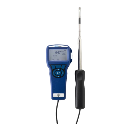
- Page 1 VELOCICALC ® AIR VELOCITY METER MODEL 9535/9535-A OPERATION AND SERVICE MANUAL P/N 1980563, REVISION J NOVEMBER 2020 GlobalTestSupply www. .com uality Products Online at: sales@GlobalTestSupp...
- Page 2 GlobalTestSupply www. .com uality Products Online at: sales@GlobalTestSupp...
- Page 3 Copyright TSI Incorporated / 2007-2020 / All rights reserved. LIMITATION OF WARRANTY AND LIABILITY (effective February 2015) Seller warrants the goods, excluding software, sold hereunder, under normal use and service as described in the operator's manual, to be free from defects in workmanship and material for 24 months, or if less, the length of time specified in the operator's manual, from the date of shipment to the customer.
- Page 4 BUSINESS INTERRUPTION, OR ANY SPECIAL, INDIRECT, CONSEQUENTIAL OR INCIDENTAL DAMAGES. SELLER SHALL NOT BE RESPONSIBLE FOR INSTALLATION, DISMANTLING OR REINSTALLATION COSTS OR CHARGES. No Action, regardless of form, may be brought against Seller more than 12 months after a cause of action has accrued.
-
Page 5: Table Of Contents
CONTENTS CHAPTER 1 UNPACKING AND PARTS IDENTIFICATION .... 1 CHAPTER 2 SETTING-UP ..............3 Supplying Power to the Model 9535/9535-A ........3 Installing the Batteries ............... 3 Using the Optional AC Adapter ..........3 Using the Telescoping Probe ............3 Extending the Probe .............. -
Page 6: Chapter 1 Unpacking And Parts Identification
Chapter 1 Unpacking and Parts Identification Carefully unpack the instrument and accessories from the shipping container. Check the individual parts against the list of ® components. If anything is missing or damaged, notify TSI Incorporated immediately. 1. Carrying case 2. Instrument 3. -
Page 7: Chapter 2 Setting-Up
Chapter 2 Setting-up Supplying Power to the Model 9535/9535-A ® ® The TSI Model 9535/9535-A VelociCalc Air Velocity Meter is powered with four size AA batteries. Installing the Batteries Insert four AA batteries as indicated by the diagram located on the inside of the battery compartment. -
Page 8: Connecting To A Computer
Connecting to a Computer Use the Computer Interface USB Cable provided with the Model 9535/9535-A to connect the instrument to a computer for downloading stored data. For more information on how to download stored data see Chapter 3 LogDat2™ Downloading Software. -
Page 9: Chapter 3 Operation
Chapter 3 Operation Keypad Functions Press to turn the Model 9535/9535-A on and off. ON/OFF Key During the power up sequence the display will show the following: Model Number, Serial Number, Software Revision and Last Date Calibrated. Press to scroll through choices while setting a Arrow () Keys parameter. -
Page 10: Menus
Menus DISPLAY SETUP Display setup menu is where you will setup the desired parameters to be displayed on the running screen. With a parameter highlighted you can then use the ON soft key to have it show up on the running screen or select the OFF soft key to turn off the parameter. -
Page 11: Data Logging
DATA LOGGING Measurements Measurements to be logged are independent of measurements on the display, and must therefore be selected under DATA LOGGING → Measurements. Delete Data Use this to delete all data, delete test or delete sample. % Memory This option displays the memory available. Delete All, under Delete Data, will clear memory and reset the memory available. -
Page 12: Chapter 4 Maintenance
Chapter 4 Maintenance The Model 9535/9535-A requires very little maintenance to keep it performing well. Recalibration To maintain a high degree of accuracy in your measurements, we ® recommend that you return your Model 9535/9535-A to TSI Incorporated for annual recalibration. Please contact one of TSI’s offices or your local distributor to make service arrangements and to receive a “Service Request”... -
Page 13: Chapter 5 Troubleshooting
Chapter 5 Troubleshooting Table 5-1 lists the symptoms, possible causes, and recommended solutions for common problems encountered with the Model 9535/9535-A. If your symptom is not listed, or if none of the solutions ® solves your problem, please contact TSI Incorporated. -
Page 14: Appendix A Specifications
Appendix A Specifications Specifications are subject to change without notice. Velocity: Range: 0 to 6000 ft/min (0 to 30 m/s) 1&2 Accuracy ±3% of reading or ±3 ft/min (±0.015 m/s), whichever is greater Resolution: 1 ft/min (0.01 m/s) Duct Size: Range: 1 to 250 inches in increments of 0.1 in. - Page 15 External Meter Dimensions: 3.3 in. 7.0 in. 1.8 in. (8.4 cm 17.8 cm 4.4 cm) Meter Probe Dimensions: Probe length: 40 in. (101.6 cm) Probe diameter of tip: 0.28 in. (7.0 mm) Probe diameter of base: 0.51 in. (13.0 mm) Articulating Probe Dimensions: Articulating section length: 6.0 in.
Need help?
Do you have a question about the VELOCICALC 9535-A and is the answer not in the manual?
Questions and answers